Pharmacology Notes -Apoptosis {CANCER} Steps Examples Pathway Mechanism Apoptosis vs Necrosis PDF PPT

What is Apoptosis PDF PPT.PNG

Pharmacology Notes

Apoptosis

Apoptosis is the programmed cell death. It is used by organisms to control the number of cells and tissue size. The cells during apoptosis shrink, but no uncontrolled release of cell debris into the environment occurs. The immune system usually “cleans up” the dying cells, and the content is recycled.

Apoptosis is triggered by an extracellular signal to the CD95 receptor. In response to that signal a set of cysteine proteases, called caspases are activated, that are largely responsible for the morphological changes observed.

Apoptosis Mechanism steps Examples Cancer & Apoptosis PPT PDF

Routes for Apoptosis:

•Two pathways for activation:
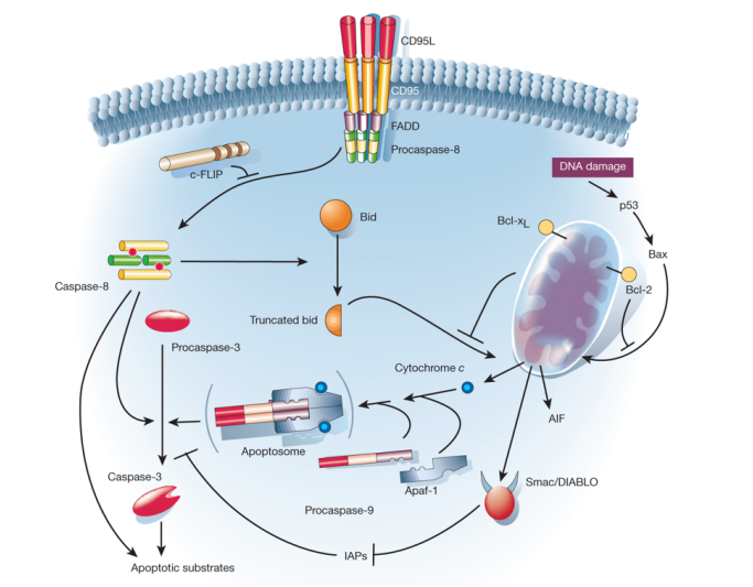
i) at the plasma membrane via external ligands upon binding to the death receptor or
ii) via the mitochondrial pathway

•Binding of external ligands such as tumor necrosis factor receptor (TNFα) to Fas receptors of the TNF superfamily induces receptor oligomerization and formation of a death-inducing signaling complex. This complex recruits, via the adaptor molecule FADD (Fas-associated death domain) multiple Pro-caspase-8 molecules, resulting in caspase-8 activation that finally results in caspase-3 activation

•In the mitochondrial pathway release of apoptogenic factors such as cytochrome c, Apaf-1, caspase-9-containing apoptosome complex and inhibitors-of-apoposis proteins trigger caspase-3 activation

• Links between the two pathways exist. 

What is Apoptosis PDF PPT.PNG

Apoptosis

Regulators of Apoptosis

• The Bcl-2 family of factors regulate caspase activation either negatively ( e.g. Bcl-2, Bcl-XL, MCL1) or positively (e.g. Bcl-XS, Bax,
BAD, BAK, BID)
• The inhibitors of apoptosis proteins (IAP) retard apoptosis
• Upstream modulators are oncogenes such as c-myc, that activates apoptosis in a manner important in cancer therapy • the tumor suppressor p53 induces apoptosis under certain circumstances 

Apoptosis {CANCER} Steps Examples Pathway Mechanism Apoptosis vs Necrosis PDF PPT

Terms:

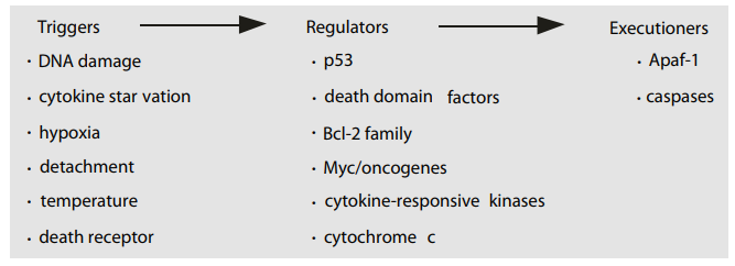
Triggers Regulators Executioners
DNA damage
cytokine star vation
hypoxia
detachment
temperature
death receptor
p53
death domain factors
Bcl-2 family
Myc/oncogenes
cytokine-responsive kinases
Apaf-1
caspases
cytochrome c

Incoming Searches

apoptosis examples

apoptosis mechanism

why is apoptosis important

apoptosis steps

apoptosis pathway

apoptosis pdf

apoptosis cancer

apoptosis vs necrosis

Apoptosis vs Necrosis

• Necrosis is the uncontrolled (pathological) cell death. In contrast with apoptosis, cleanup of cell debris by phagocytes of the immune system is generally more difficult. There are many causes of necrosis including injury, infection, cancer, infarction, toxins and inflammation. Necrosis can arise from lack of proper care to a wound site. Usually cell outlines do not stay intact, and cell debris is released into the environment
• Apoptosis is the programmed cell death. It is used by organisms to control the number of cells and tissue size. The cells during apoptosis shrink, but no uncontrolled release of cell debris into the environment occurs. The immune system usually “cleans up” the dying cells, and the content is recycled. Apoptosis is triggered by an extracellular signal to the CD95 receptor. In response to that signal a set of cysteine proteases, called caspases are activated, that are largely responsible for the morphological changes observed.

ANATOMY & PHYSIOLOGY Of Human Respiratory Tract

ANATOMY & PHYSIOLOGY Of Human Respiratory Tract

Anatomy and Physiology Of human respiratory system is a complicated organ system of very close structure– function relationships. The system consisted of two regions: the conducting airway and the respiratory region. The airway is further divided into many folds: nasal cavity and the associated sinuses, and the nasopharynx, oropharynx, larynx, trachea, bronchi, and bronchioles. The respiratory region consists of respiratory bronchioles, alveolar ducts, and alveolar sacs.

ANATOMY AND PHYSIOLOGY OF HUMAN RESPIRATORY TRACT:

               The respiratory system works with the circulatory system to deliver oxygen from the lungs to the cells and remove carbon dioxide, and return it to the lungs to be exhaled. The exchange of oxygen and carbon dioxide between the air, blood and body tissues is known as respiration. Healthy lungs take in about 1 pint of air about 12–15 times each minute. All of the blood in the body is passed through the lungs every minute. The respiratory tract is divided into two main parts: the upper respiratory tract, consisting of the nose, nasal cavity and the pharynx; and the lower respiratory tract consisting of the larynx, trachea, bronchi and the lungs The trachea, which begins at the edge of the larynx, divides into two bronchi and continues into the lungs. The trachea allows air to pass from the larynx to the bronchi and then to the lungs. The bronchi divide into smaller bronchioles which branch in the lungs forming passageways for air. The terminal parts of the bronchi are the alveoli. The alveoli are the functional units of the lungs and they form the site of gaseous exchange     

ANATOMY & PHYSIOLOGY Of Human Respiratory Tract

            The blood barrier between the alveolar space and the pulmonary capillaries is very thin to allow for rapid gas exchange. During inspiration, oxygen diffuses through the alveoli walls and the interstitial space, into the blood. Carbon dioxide diffuses in the opposite direction during exhalation. Alveoli are small and there are approximately 300 million of them in each lung. Although alveoli are tiny structures, they have a very large surface area in total (~100 m2) for performing efficient gas exchange.

                     The alveoli form a honeycomb of cells around the spiral, cylindrical surface of the alveolar duct. The exposed alveolar surface is normally covered with a surface film of lipoprotein material.

                      There are several types of pulmonary alveolar cells. Type I (or small type A), are non-phagocytic, membranous pneumocytes. These surface-lining epithelial cells are approximately 5 μm in thickness and possess thin squamous cytoplasmic extensions that originate from a central nucleated portion. These portions do not have any organelles and hence they are metabolically dependent on the central portion of the cell. This reduces their ability to repair themselves if damaged. Attached to the basement membrane are the larger alveolar cells (Type II, type B or septal cells). These rounded, granular, epithelial pneumocytes are approximately 10 to 15 μm tick. There are 6 to 7 cells per alveolus and these cells possess great metabolic activity. They are believed to produce the surfactant material that lines the lung and to be essential for alveolar repair after damage from viruses or chemical agents.

             Amongst, the important roles of the lungs, one can cite: (i) supply oxygen, (ii) remove wastes and toxins, and (iii) defend against hostile intruders. The lungs have three dozen distinct types of cells. Some of these cells scavenge foreign matter. Others have cilia that sweep the mucous membranes lining the smallest air passages. Some cells act on blood pressure control, while others spot infection invaders.

 anatomy of lungs            

      The respiratory system is susceptible to a number of diseases, and the lungs are prone to a wide range of disorders caused by genetic factors, infection and pollutants in the air. The most common problems of the respiratory system are:

  • Asthma
  • Bronchiolitis
  • Chronic obstructive pulmonary disease (COPD)
  • Common cold
  • Cough
  • Cystic fibrosis (CF)
  • Lung cancer
  • Pneumonia
  • Pulmonary hypertension

PRINCIPAL MECHANISMS OF RESPIRATORY DEPOSITION

            The deposition of inhaled particles in the different regions of the respiratory system is very complex, and depends on many factors. Some of the factors influencing respiratory deposition include:

  • Breathing rate
  • Mouth or nose breathing
  • Lung volume
  • Respiration volume
  • Health of the individual
  • Bifurcations in the airways result in a constantly changing hydrodynamic flow field.

Depending on the particle size, airflow, and location in the respiratory system, particle deposition occurs via on of the following principal mechanisms:

Impaction

         Each time the airflow changes due to a bifurcation in the airways, the suspended particles tend to travel along their original path due to inertia and may impact on an airway surface. This mechanism is highly dependent on aerodynamic diameter, since the stopping distance for very small particles is quite low. Impaction occurs mostly in the case of larger particles that are very close to airway walls, near the first airway bifurcations. Therefore, deposition by impaction is greatest in the bronchial region. Impaction accounts for the majority of particle deposition on a mass basis.

 Sedimentation

           Sedimentation is the settling out of particles in the smaller airways of the bronchioles and alveoli, where the air flow is low and airway dimensions are small. The rate of sedimentation is dependent on the terminal settling velocity of the particles, so sedimentation plays a greater role in the deposition of particles with larger aerodynamic diameters. Hygroscopic particles may grow in size as they pass through the warm, humid air passages, thus increasing the probability of deposition by sedimentation.

 Interception

            Interception occurs when a particle contacts an airway surface due to its physical size or shape. Unlike impaction, particles that are deposited by interception do not deviate from their air streamlines. Interception is most likely to occur in small airways or when the air streamline is close to an airway wall. Interception is most significant for fibers, which easily contact airway surfaces do to their length. Furthermore, fibers have small aerodynamic diameters relative to their size, so they can often reach the smallest airways.


Diffusion

Diffusion is the primary mechanism of deposition for particles less than 0.5 microns in diameter and is governed by geometric rather than aerodynamic size. Diffusion is the net transport of particles from a region of high concentration to a region of lower concentration due to Brownian motion. Brownian motion is the random wiggling motion of a particle due to the constant bombardment of air molecules. Diffusional deposition occurs mostly when the particles have just entered the nasopharynx, and is also most likely to occur in the smaller airways of the pulmonary (alveolar) region, where air flow is low.


 Absorption – bioavailability of drugs

Although inhaled drugs have been used for over 50 years to treat airway disease and are in development or being considered for the treatment of many other lung diseases, insulin is at present time the only one representative inhaled drug on the market for systemic disease. Exubera® (insulin human [rDNA origin] inhalation powder is the first diabetes treatment which can be inhaled. Exubera® helps control high blood sugar, works in adults with type 1 diabetes and with type 2 diabetes as well This therapeutic success has lead a number of other companies to investigate and to advance clinical trials as inhaled formulations for systemic applications with a variety of large molecules (leuprolide, a luteinizing hormone-releasing hormone (LHRH) analogue, …). Recent advances in the development of particle technologies and devices now make it possible to formulate, stabilize, and accurately deliver almost any drug to the lungs.

             The pulmonary membrane is naturally permeable to small molecule drugs and to many therapeutic peptides and proteins. The epithelium of the lung, the significant barrier to absorption of inhaled drugs, is thick (50–60 μm) in the trachea, but diminishes in thickness to an extremely thin 0.2 μm in the alveoli. The change in cell types and morphology going from trachea, bronchi, and bronchioles to alveoli is very dramatic. The lungs are for more permeable to macromolecules than any other portal of entry into the body. Some of the most promising therapeutic agents are peptides and proteins, which could be inhaled instead of injected, thereby improving compliance .Particularly, peptides that have been chemically altered to inhibit peptidase enzymes exhibit very high bioavailabilities by the pulmonary route .Indeed, natural mammalian peptides, les than 30 amino acids (somatostatin, vaso active intestinal peptide [VIP], and glucagons), are broken down in the lung by ubiquitous peptidases and have very poor bioavailabilities. Conversely, proteins with molecular weights between 6000 and 50,000 Da are relatively resistant to most peptidases and have good bioavailabilities following inhalation. For larger proteins, the bioavailabilities and absorption mechanisms are not well completely elucidated.

ADVANTAGES OF PULMONARY DRUG DELIVERY SYSTEM


  1. The ability to nebulize viscous drug formulations for pulmonary delivery, thereby overcoming drug solubility issues with the ability to use lipid, water or lipid/water emulsions as drug carriers.
  2. Ability to nebulize viscous liquids into droplets in the 2-5μm range regardless of the carrier composition solubility which would allow for a wide range of drug formulation options.
  3. Increased drug delivery efficacy due to size-stable aerosol droplets with reduced

hygroscopic growth and evaporative shrinkage.

  1. Liposomal drug formulations remain stable when nebulized.
  2. Ability to nebulize protein-containing solutions.
  3. For hand held inhaler applications, drug does not need to be emulsified in liquefied nebulizing gas to achieve aerosolization.

Pharmaceutical Water Systems: Pharmaceutical Water Storage & Distribution Systems [PDF PPT]

Pharmaceutical Water Systems Pharmaceutical Water Storage & Distribution Systems [PDF PPT]

Water storage and distribution systems

Pharmaceutical Water Systems:: Water storage and distribution systems applies to WPU systems for PW, BHPW and BWFI. The water storage and distribution should work in conjunction with the purification plant to ensure delivery of water of consistent quality to the user points, and to ensure optimum operation of the water purification equipment.

General Principles of Water storage and distribution systems of Pharmaceutical Water Systems:

  1. The storage and distribution system should be considered as a key part of the whole system and should be designed to be fully integrated with the water purification components of the system.
  2. Once water has been purified using an appropriate method it can either be used directly or, more frequently, it will be fed into a storage vessel for subsequent distribution to points of use. The the requirements for storage and distribution systems and point of use fflPOU) is provided below.
  3. The storage and distribution system should be configured to prevent microbial proliferation and recontamination of the water fflPW, BHPW, BWFI) treatment. It should be subjected to a combination of online and offline monitoring to ensure that the appropriate water specification is maintained.

2 Materials that come into contact with systems for water for pharmaceutical use in Pharmaceutical Water Systems:

Here we deal with generation equipment for PW, BHPW and BWFI and the associated storage and distribution systems.

2.2 The materials that come into contact with WPU, including pipework, valves and fittings, seals, diaphragms and instruments, should be selected to satisfy the following objectives.

Compatibility.

The compatibility and suitability of the materials should encompass the full range of its working temperature and

potential chemicals that will come into contact with the system at rest, in operation and during sanitization.

Prevention of leaching.

All materials that come into contact with WPU should be non-leaching at the range of working and sanitization

temperatures of the system.

Corrosion resistance.

PW, BHPW and BWFI are highly corrosive. To prevent failure of the system and contamination of the water, the materials selected must be appropriate, the method of jointing must be carefully controlled and all fittings and components must be compatible with the pipework used. Appropriate sanitary specification plastics and stainless-steel materials are acceptable for WPU systems. When stainless steel is used it should be at least grade 316. In general 316L or a higher grade of stainless steel is used. The system should be passivated after initial installation or after significant modification. When accelerated passivation is undertaken the system should be thoroughly cleaned first and the passivation process should be undertaken in accordance with a clearly defined documented procedure.

Smooth internal Finish.

Once water has been purified it is susceptible to microbiological contamination and the system is subject to the formation of biofilms when cold storage and distribution are employed. Smooth internal surfaces help to avoid roughness and crevices within the WPU system. Crevices can be the source of contamination because of possible accumulation of microorganisms and formation of biofilms. Crevices are also frequently sites where corrosion can commence. The internal material finish should have an arithmetical average surface roughness of not greater than 0.8 micrometre fflRa). When stainless steel is used, mechanical and electro-polishing techniques may be employed. Electro-polishing improves the resistance of the stainless-steel material to surface corrosion.

Jointing.

The selected system materials should be easily joined by welding in a controlled manner. The control of the process should include, as a minimum, qualification of the operator, documentation  of the welder set-up, work session test pieces logs of all welds and visual inspection of a defined proportion of welds, e.g. 100ft hand welds, 10ft automatic welds.

Documentation.

All system components should be fully documented and be supported by original or certified copies of material certificates.

Materials used for Pharmaceutical Water Systems:

Suitable materials that may be considered for sanitary elements of the system include 316L ffllow carbon) stainless steel, polypropylene, polyvinylidene-diFluoride and perFluoroalkoxy. The choice of material should take into account the intended sanitization method. Other materials such as unplasticized polyvinyl-chloride ffluPVC) may be used for treatment equipment designed for less pure water such as ion exchangers and softeners.

None of the materials that come into contact with WPU should contain chemicals that will be extracted by the water. Plastics should be non-toxic and should be compatible with all chemicals used. They should be manufactured from materials that should at least meet minimum food grade standards. Their chemical and biological characteristics should meet any relevant pharmacopoeia specifications or recommendations. Precautions should be taken to define operational limits for areas where water circulation is reduced and turbulent Flow cannot be achieved. Minimum Flow rate and change volumes should be defined.

3. System sanitization and bioburden control -Pharmaceutical Water Systems:

1 Water treatment equipment, storage and distribution systems used for BPW, BHPW and BWFI should be provided with features to control the proliferation of microbiological organisms during normal use, as well as techniques for sanitizing the system after intervention for maintenance or modification. The techniques employed should be considered during the design of the system and should take into account the interdependency between the materials and the sanitization techniques.

2 Systems that operate and are maintained at elevated temperatures ffle.g. > 65) are generally less susceptible to microbiological contamination than systems that are maintained at lower temperatures. When lower temperatures are required due to the water treatment processes employed or the temperature requirements for the water in use, special precautions should be taken to prevent the ingress and proliferation of microbiological contaminants fflsee section 6.4.3 for guidance).

4 Storage vessel requirements -Pharmaceutical Water Systems:

1 General

1 The water storage vessel used in a system serves a number of important functions. The design and size of the vessel should take into consideration the following.

2 Capacity

1 The capacity of the storage vessel should be determined on the basis of the following requirements:

It is necessary to provide a buffer capacity between the steady-state generation rate of the water-treatment equipment and the potentially variable simultaneous demand from user points.

The water-treatment equipment should be able to operate continuously for significant periods to avoid the equipment stress that occur when the equipment cycles on and off too frequently.

The capacity should be suffcient to provide short-term reserve capacity in the event of failure of the water-treatment equipment or inability to produce water due to a sanitization or regeneration cycle. When determining the size of such reserve capacity, consideration should be given to providing suffcient water to complete a process batch, work session, tank turnover by recirculation to minimize stagnation, or other logical period of demand.

3 Contamination control considerations -Pharmaceutical Water Systems:

The following should be taken into account for the efficient control of contamination:

) The headspace in the storage vessel is an area of risk where water droplets and air can come into contact at temperatures that encourage the proliferation of microbiological organisms. The use of spray-ball or distributor devices should be considered in these systems to wet the surfaces during normal operation, chemical and/or thermal sanitization.

) Nozzles within the storage vessels should be configured to avoid dead zones where microbiological contamination might be harboured.

) Vent filters are fitted to storage vessels to allow the internal level of liquid to Fluctuate. The filters should be bacteria-retentive, hydrophobic and should ideally be configured to allow in situ testing of integrity. Offline testing is also acceptable. The use of heated vent filters should be considered for continuous hot storage or systems using periodic heat sanitization to prevent condensation within the filter matrix that might lead to filter blockage and to microbial growth that could contaminate the storage vessels.

) Where pressure-relief valves and bursting discs are provided on storage vessels to protect them from under- and over-pressurization, these devices should be of a sanitary design. Bursting discs should be provided with external rupture indicators to ensure that loss of system integrity is detected.

Requirements for water distribution pipework -Pharmaceutical Water Systems:

General

The distribution of BPW, BHPW and BWFI should be accomplished using  a continuously circulating pipework loop. Proliferation of contaminants within the storage tank and distribution loop should be controlled. Good justification for using a non-recirculating one-way system should be provided.

2 Filtration should not usually be used in distribution loops or at take off-user points to control biocontamination. Such filters are likely to conceal system contamination.

Temperature control and heat exchangers

Where heat exchangers are employed to heat or cool WPU within a system, precautions should be taken to prevent the heating or cooling utility from contaminating the water. The more secure types of heat exchangers of the double tube plate or double plate and frame or tube and shell configuration should be considered. Where these types are not used, an alternative approach whereby the utility is maintained and monitored at a lower pressure than the WPU may be considered. The latter approach is not usually adopted in BWFI systems.

Where heat exchangers are used they should be arranged in continually circulating loops or subloops of the system to avoid unacceptable static water in systems.

When the temperature is reduced for processing purposes the reduction should occur for the minimum necessary time. The cooling cycles and their duration should be proven satisfactory during the qualification of the system.

Pharmaceutical Water Systems Pharmaceutical Water Storage & Distribution Systems [PDF PPT]

3 Circulation pumps

Circulation pumps should be of a sanitary design with appropriate seals that prevent contamination of the system. Where stand-by pumps are provided, they should be configured or managed to avoid dead zones trapped within the system.

Consideration should be given to preventing contamination in systems where parallel pump systems are used, especially if there is stagnant water when one of the pumps is not being used.

4 Biocontamination control techniques

1 Water purification systems should be sanitized using chemical or thermal sanitization procedures as appropriate fflproduction and distribution). The procedure and conditions used fflsuch as times and temperatures) should be suitable.

2 The following control techniques may be used alone or more commonly in combination:

maintenance of continuous turbulent flow circulation within water distribution systems reduces the propensity for the formation of biofilms the system design should ensure the shortest possible length of pipework;

) for ambient temperature systems, pipework should be isolated from adjacent hot pipes;

) dead legs in the pipework should be minimized through appropriate design, and as a guide should not significantly exceed three times the branch diameter as measured from the ID pipe wall to center line of the point-of-use valve where significant stagnation potential exists;

) pressure gauges should be separated from the system by membranes;

) hygienic pattern diaphragm valves should be used;

) pipework for steam-sanitized systems should be sloped and fully drainable;

) the growth of microorganisms can be inhibited by:

– ultraviolet radiation sources in pipework;

– maintaining the system heated fflgreater than 65 °C);

– sanitizing the system periodically using hot water guidance temperature > 70’°C);

– sanitizing the system periodically using superheated hot water or clean steam;

– routine chemical sanitization using ozone or other suitable chemical agents. When chemical sanitization is used, it is essential to prove that the agent has been removed prior to using the water. Ozone can be effectively removed by using ultraviolet radiation.

Incoming searches for Pharmaceutical Water Systems:

Pharmaceutical Water Systems Pharmaceutical Water Storage & Distribution Systems PDF PPT

Pharmaceutical Water Systems Pharmaceutical Water Storage & Distribution Systems  PPT

Pharmaceutical Water Systems

Purified Water Specification As Per Usp

Pharmaceutical Water System Design Operation And Validation Pdf

pharmaceutical water system design operation and validation

pharmaceutical water system ppt – What is Pharmaceutical water

purified water ff Water for Injection SOP as per usp

Pharmaceutical Water Systems: Storage ff Distribution Systems

pharmaceutical water system : Inspection of Pharmaceutical water systems

pharmaceutical water Production : Water purification systems

Pharmaceutical Water Systems: Types: Water quality specifications

Pharmaceutical Water System: principles for pharmaceutical water systems

Source: WHO

[PDF PPT DOC] Pharmaceutical FILTER VALIDATION – Sterile Protocol FDA Guide

Pharmaceutical FILTER VALIDATION PDF DOC PPT- Sterile Protocol FDA Guide

FILTER VALIDATION

Do you know Pharmaceutical Filter validation importance? Pharmaceutical processes are validated processes to assure a reproducible product  within set specifications. Equally important is the validation of the filters used within the process, especially the sterilizing grade filters, which, often enough, are used before filling or the final processing of the drug product. In its Guideline on General Principles of Process Validation, 1985, and Guideline on Sterile Drug Products Produced by Aseptic Processing, 1987, the FDA makes plain that the validation of sterile processes is required by the manufacturers of sterile products. Sterilizing grade filters are determined by the bacteria challenge test. This test is performed under strict parameters and a defined solution (ASTM F 838-83).

In any case, the FDA nowadays also requires evidence that the sterilizing grade filter will create a sterile filtration, no matter the process, fluid or bioburden, found. This means that bacteria challenge tests have to be performed with the actual drug product, bioburden, if different or known to be smaller than B. diminuta and the process parameters. The reason for the requirement of a product bacteria challenge test is threefold. First, the influence of the product and process parameters to the microorganism has to be tested. There may be cases of either shrinkage of organisms due to a higher osmolarity of the product or prolonged processing times. Second, the filter’s compatibility with the product and the parameters has to be tested. The filter should not show any sign of degradation due to the product filtered. Additionally, rest assurance is required that the filter used will withstand the process parameters; e.g., pressure pulses, if happening, should not influence the filter’s performance.

Third, there are two separation mechanisms involved in liquid filtration: sieve retention and retention by adsorptive sequestration. In sieve retention, the smallest particle or organism size is retained by the biggest pore within the membrane structure. The contaminant will be retained, no matter the process parameters. This is the ideal. Retention

by adsorptive sequestration depends on the filtration conditions. Contaminants smaller than the actual pore size penetrate such and may be captured by adsorptive attachment to the pore wall. This effect is enhanced using highly adsorptive filter materials, for example,

Glassfibre as a prefilter or Polyamide as a membrane. Nevertheless, certain liquid properties can minimize the adsorptive effect, which could mean penetration of organisms. Whether the fluid has such properties and will lower the effect of adsorptive sequestration and may eventually cause penetration has to be evaluated in specific product bacteria challenge tests.

[PDF PPT DOC] FILTER VALIDATION - Sterile Protocol FDA Guide

Before performing a product bacteria challenge test, it has to be assured that the liquid product does not have any detrimental, bactericidal or bacteriostatic, effects on the challenge organisms. This is done utilizing viability tests. The organism is inoculated into the product

to be filtered at a certain bioburden level. At specified times, the log value of this bioburden is tested. If the bioburden is reduced due to the fluid properties, a different bacteria challenge test mode becomes applicable. If the reduction is a slow process, the challenge test will

be performed with a higher bioburden, bearing in mind that the challenge level has to reach 107 per square centimeter at the end of the processing time. If the mortality rate is too high, the toxic substance is either removed or product properties are changed. This challenge fluid is called a placebo. Another methodology would circulate the fluid product through the filter at the specific process parameters as long as the actual processing time would be. Afterwards, the filter is flushed extensively with water and the challenge test, as described in ASTM F838-38, performed. Nevertheless, such a challenge test procedure would be more or less a filter compatibility test.

Besides the product bacteria challenge test, tests of extractable substances or  articulate releases have to be performed. Extractable measurements and the resulting data are available from filter manufacturers for the individual filters. Nevertheless, depending

on the process conditions and the solvents used, explicit extractable tests have to be  performed. These tests are commonly done only with the solvent used with the drug product but not with the drug ingredients themselves, because the drug product usually

covers any extractables during measurement. Such tests are conducted by the validation services of the filter manufacturers using sophisticated separation and detection methodologies, as GC-MS, FTIR, and RP-HPLC. These methodologies are required, due to the fact that the individual components possibly released from the filter have to be identified and quantified. Elaborate studies, performed by filter manufacturers, showed that there is neither a release of high quantities of extractables (the range is ppb to max ppm per 10-inch element) nor have toxic substances been found. Particulates are critical in sterile filtration, specifically of injectables. The USP 24 (United States Pharmacopoeia) and BP (British Pharmacopoeia) quote specific limits of particulate level contaminations for defined particle sizes. These limits have to be kept and, therefore, the particulate release of sterilizing

grade filters has to meet these requirements. Filters are routinely tested by evaluating the filtrate with laser particle counters. Such tests are also performed with the actual product under process conditions to prove that the product, but especially process conditions, do

not result in an increased level of particulates within the filtrate.

Additionally, with certain products, loss of yield or product ingredients due to adsorption shall be determined. For example, preservatives, like  benzalkoniumchloride or chlorhexadine, can be adsorbed by specific filter membranes. Such membranes need to be saturated by the preservative to avoid preservative loss within the actual product. This preservative loss e.g., in contact lens solutions, can be detrimental, due

to long-term use of such solutions. Similarly, problematic would be the adsorption of required proteins within a biological solution. To optimize the yield of such proteins within an application, adsorption trials have to be performed to find the optimal membrane

material and filter construction.

Cases that use the actual product as a wetting agent to perform integrity tests require the evaluation of product integrity test limits. The product can have an influence on the measured integrity test values due to surface tension, or solubility. A lower surface tension,

for example, would shift the bubble point value to a lower pressure and could result in a false negative test. The solubility of gas into the product could be reduced, which could result in false positive diffusive flow tests. Therefore, a correlation of the product as a wetting agent to the, water wet values has to be done, according to standards set by the manufacturer of the filter. This correlation is carried out by using a minimum of three filters of three filter lots. Depending on the  product and its variability, one or three product lots are used to perform the correlation. The accuracy of such a correlation is enhanced by automatic integrity test

machines. These test machines measure with highest accuracy and sensitivity and do not rely on human judgement, as with a manual test. Multipoint diffusion testing offers the ability to test the filter’s performance and, especially, to plot the entire diffusive flow graph through the bubble point. The individual graphs for a water-wet integrity test can now be compared to the product wet test and a possible shift evaluated. Furthermore, the multipoint diffusion test enables the establishment of an improved statistical base to determine the product wet versus water-wet limits.

Look out here Pharmaceutical FILTER INTEGRITY TESTING – FDA Guideline on Sterile Drug Products

Pharmaceutical Filter Validation References:

  1. Cooper and Gunn’s. Tutorial Pharmacy by S.J.Carter.
  2. Pharmaceutical engineering; K. Sambamurthy
  3. Pharmaceutical engineering; principles and practices, C.V.S. Subrahmanyam
  4. Encyclopedia of pharmaceutical technology, vol 3, edited by James Swarbrick.
  5. Pikal, M.J.; Lukes, A.L.; Lang, J.E. Thermal decomposition of amorphous beta-lactam antibacterials. J. Pharm. Sci. 1977, 66, 1312–1316.
  6. Pikal, M.J.; Lukes, A.L.; Lang, J.E.; Gaines, K. Quantitative crystallinity determinations of beta-lactam antibiotics by solution calorimetry: correlations with stability. J. Pharm. Sci. 1978, 67, 767–773.
  7. Pikal, M.J.; Dellerman, K.M. Stability testing of pharmaceuticals by high-sensitivity isothermal calorimetry at 25_C: cephalosporins in the solid and aqueous solution states. Int. J. Pharm. 1989, 50, 233–252.
  8. Incoming searches:
  9. filter validation ppt,
    filter validation pdf,
    brevundimonas diminuta filter validation,
    filter validation millipore,
    filter validation fda,
    sterile filtration validation protocol,
    bacterial retention testing of sterilizing-grade filters,
    sterile filtration definition,

Pharmaceutical Filter validation pdf:

Pharmaceutical filter validation ppt filter validation power point

Pharmaceutical filter validation ppt filter

Pharmaceutical filter validation ppt filter validation pdf

Pharmaceutical filter validation ppt filter validation power point

{PDF PPT DOC} FILTRATION EQUIPMENT – Filtration Mechanism & Types – Adv + Disadvantages

{PDF PPT DOC} FILTRATION EQUIPMENT – Filtration Mechanism & Types – Adv + Disadvantages deals with details of filtration, filtration equipment,definitions, mechanism of filtration, Classification of filtration equipment, Different types of filtration its advantages & Disadvantages.

FILTRATION Definition:

FILTRATION may be defined as the separation of a solid from a fluid by means of a porous medium that retains the solid but allows the fluid to pass.

The term fluid includes liquids and gases, so that both these may be subjected to filtration.

The suspension of solid and liquid to be filtered is known as the “slurry”. The porous medium used to retain the solids is described as the filter medium; the accumulation of solids on the filter is referred to as the filter cake, while the clear liquid passing through the filter is the filtrate.

2.MECHANISMS OF FILTRATION:

The mechanisms whereby particles are retained by the filter are of significance only in the early stages of liquid filtration, as a rule. Once a preliminary layer of particles has been deposited, the filtration is effected by the filter cake, the filter medium serving only as a support.

STRAINING:

The simplest filtration procedure is “straining”, in which, like sieving, the pores are smaller than the particles, so that the latter are retained on the filter medium.

ENTANGLEMENT:

If the filter medium consists of a cloth with a nap or a porous felt, then particles become entangled in the mass of fibres. Usually the particles are smaller than the pores, so that it is possible that impingement is involved.

ATTRACTIVE FORCES:

In certain circumstances, particles may collect on a filter medium as a result of attractive forces. The ultimate in this method is the electrostatic precipitator, where large potential differences are used to remove the particles from air streams.

In practise, the process may combine the various mechanisms, but the solids removal is effected normally by a straining mechanism once the first complete layers of solids has begun to form the cake on the filter medium.

3.CLASSIFICATION OF THE FILTRATION EQUIPMENT:

Equipment’s are classified based on the application of external force.

  1. Pressure filters: plate and frame filter press and metafilter
  2. Vacuum filters: filter leaf
  3. Centrifugal filters

Classification based on the operation of the filtration

  1. Continuous filtration: discharge and filtrate are separated steadily and uninterrupted
  2. Discontinuous filtration: discharge of filtered solids is intermittent. Filtrate is removed continuously. The operation must be stopped to collect the solids.

Classification based on the nature of filtration

  1. Cake filters: remove large amounts of solids (sludge or crystals)
  2. Clarifying filters: remove small amounts of solids
  3. Cross-flow filters: feed of suspension flows under pressure at a fairly high velocity across the filter medium.

Equipment’s of pharmaceutical interest:

  1. Sand filters:
  2. Filter presses: chamber, plate and frame filters ( non-washing/washing; closed delivery/open delivery)
  3. Leaf filters
  4. Edge filters: stream line and meta filters
  5. Rotary continuous filters
  6. Membrane filters
  1. FILTRATION EQUIPMENT:

  2. {PDF PPT DOC} FILTRATION EQUIPMENT - Filtration Mechanism & Types - Adv + Disadvantages

4.1.SAND FILTERS


These are used mainly when relatively small amounts of solid are to be removed from the liquid and when relatively large volumes of liquid must be handled at minimum cost. A standardised pressure sand filter consists of a cylindrical tank at the bottom of which are a number of brass strainers which are either mounted on a false bottom or connected to a manifold embedded in concrete. The strainers have narrow slots sawed in them. Over the strainers is a layer of several inches of moderately coarse gravel on the top of which is a 2 to 4 ft. deep sand layer that forms the actual filter medium. The water to be filtered is introduced at the top on to a baffle which prevents disturbance in the sand by a direct stream. The filtered water is drawn off through the strainers at the bottom. When the precipitate clogs the sand to the extent of retarding the flow of water, it is removed by back washing. This operation consists of introducing water through the strainers, so that it may flow up through the sand bed and-out through the connection that is normally the inlet. This wash water is wasted. These sand filters are applicable only to the separation of precipitates that can be removed from the sand in this manner and that are to be discarded. Gelatinous precipitates or precipitates that coat the sand so that they cannot be removed by back washing or precipitates that are to be recovered cannot be handled in the sand filter.

Capacity is usually 2 to 4 gpm/sq.ft of surface of filtering area.

Fig1: pressure sand filter

For filtering excessively large quantities of very clean water, an open or rapid sand filter is used. It is similar to the pressure sand filter except that the sand is contained in large, open concrete boxes instead of in a closed pressure tank. Sand filter used in this way becomes a gravity filter (also called hydrostatic head filter).

ADVANTAGES:

Gravity filters have advantages of extreme simplicity, needing only simple accessories, low first cost and can be made of almost any material.

DISADVANTAGES:

  • Relatively low rate of filtration.
  • Excessive floor area needed and high labour charges
  • If the amount of particulate matter to be removed is too small or it is finely divided, sand filter will not remove the suspended solids.
  • In processes involving organic materials there may be danger of bacterial infection from an infected process-water supply and the sand filter cannot remove the bacteria as such. In these cases a coagulant like ferrous sulphate or aluminium sulphate is added to the water before filtration. These are hydrolysed by the alkalinity of most normal waters with the formation of a flocculant precipitate of iron or aluminium hydroxide. This precipitate adsorbs finely divided suspended matter and even bacteria, even if added to the water in very small amounts. The resultant flocs, though fine, are removed by the sand filters.

4.2.PLATE AND FRAME FILTER PRESS:

.

Principle : The mechanism is surface filtration. The slurry enters the frame by pressure and flows through the filter medium: The filtrate is collected on the plates and sent to the outlet. A number of frames and plates are used so that surface area increases and consequently large volumes of slurry can be processed simultaneously with or without washing.

Construction .: The construction of a plate and frame filter press is shown in the figure2. The filter press is made of two types of units, plates and frames.

(a) Frame-Maintains the slurry reservoir, inlet (eye) for slurry.

(b) Filter medium.

(c) Plate along with section-supports the filter medium, receiving the filtrate and outlet (eye).. (d) Assemb1y of plate and frame filter press.

These are usually made of aluminium alloy. Sometimes these are also lacquered for protection against corrosive chemicals and made suitable for steam sterilisation.

Frame contains an open space inside wherein the slurry reservoir is maintained for filtration and an inlet to receive the slurry. It is indicated by two dots in the description (Figure ).The plate has a studded or grooved surface to support the filter cloth and an outlet. It is indicated by one dot in the description (Figure ). The filter medium (usually cloth) is interposed between plate and frame.

Frames of different thicknesses are available. It is selected based on the thickness of the cake formed during filtration. Optimum thickness of the frame should be chosen. Plate, filter medium, frame, filter medium and plate are arranged in the sequence and clamped to a supporting structure. It is normally described by dots as 1.2.1.2.1 so on. A number of plates and frames are employed so that filtration area is a large as necessary. In other words, a number of filtration units are operated in parallel. Channels for the slurry inlet and filtrate outlet can be arranged by fitting eyes to the plates and frames, these join together to form a channel. In some types, only one inlet channel is formed, while each plate is having individual outlets controlled by valves.

Working : The working of the frame and plate process can be described in two steps, namely filtration and washing of  the cake (if desirable).


Filtration operation : The working of a plate and frame press is shown in Figure. Slurry enters the frame (marked by 2 dots) from the feed channel and passes through the filter medium on to the surface of the plate (marked by I dot). The solids form a filter cake and remain in the frame. The thickness of the cake is half of the frame thickness, because on each side of the frame filtration occur. Thus, two filter cakes are formed, which meet eventually in the centre of the frame. In general, there will be an optimum thickness of filter cake for any slurry, depending on the solid content in the slurry and the resistance -of the

filter cake.

The filtrate drains between the projections on the surface of the plate and escapes from the outlet. As filtration proceeds, the resistance of the cake increase and the filtration rate decreases. At a certain point, is preferable to stop the process rather than continuing at very low flow rates. The press is emptied and the cycle is restarted.

Fig 3: plate and frame filter press

Washing operation: If it is necessary to wash the filter cake, the ordinary plate and frame press is unsatisfactory. Two cakes are built up in the frame meeting eventually in the middle. This means that flow is brought virtually to a stand still. Hence, water wash using the same channels of the filtrate is very inefficient, if not  impossible. A modification of the plate and frame press is used. For this purpose, an additional channel is included (Figure). These wash plates are identified by three dots. In half the wash  plate there is a connection from the wash water channel to the surface of the plate.

The sequence of arrangement of plates and frames can be represented by dQts as 1.2.3.2.1.2.3.2.1.2.3.2.1 so on (between I and 1,2.3.2 must be arranged). Such an arrangement is shown in Figure (a) and (b) for the operations of filtration and water washing, respectively.

The steps are as follows.

(1) Filtration proceeds in the ordinary way until the frames are filled with cake.

(2) To wash the filter cake, the outlets of the washing plates (three dots) are closed.

(3) Wash water is pumped into the washing channel. The water enters through the inlets on to the surface     of the washing (three dots) plates.

(4) Water passes through the filter cloth and enters frame (two dots) which contains the cake. Then water washes the cake, passes through the filter cloth and enters the plate (one dot) down the surface.

(5)Finally washed water escapes through the outlet of that plate.

Fig 4: plate and frame filter press with water wash facility

Thus with the help of special washing plates, it is possible for the wash-water to flow over the entire surface of washing (three dots) plate, so that the flow resistance of the cake is equal to all points. Hence, the entire cake is washed with equal efficiency.

Fig 5: principles of filtration and washing

It should be noted that water- wash is efficient only if the frames are full with filter cake. If the solids do not fill the frame completely, the wash water causes the cake to break (on the washing plate side of the frame) then washing will be less effective. Hence, it is essential to allow the frames become completely filled with the cake. This helps not only in emptying the frames but also helps in washing the cake correctly.

Special provisions:

(I) Any possible contamination can be observed by passing the filtrate through a glass tube or sight glass from the outlet on each plate. This permits the inspection of quality of the filtrate. The filtrate goes through the control valve to an outlet channel.

(2) The filtration process from each plate can be seen. In the event of a broken cloth, the faulty plate can be isolated and filtration can be continued with one plate less.

Uses : Filter sheets composed of asbestos and cellulose are capable of retaining bacteria, so that sterile filtrate can be obtained, provided that the whole filter press and filter medium have been previously sterilized. Usually steam is passed through the assembled unit for sterilization.

Examples include collection of precipitated antitoxin, removal of precipitated proteins from insulin liquors and removal of cell broth from the fermentation medium.

Heating/cooling coils are incorporated in the press so as to make it suitable for the filtration of viscous liquids .

Advantages :

(1) Construction of filter press is very simple and a variety of materials can be used.

– Cast iron for handling common substances.

— Bronze for smaller units.

– Stainless steel is used there by contamination can be avoided.

– Hard rubber or plastics where metal must be avoided.

– Wood for lightness though it must be kept wet.

(2) It provides a large filtering area in a relatively small floor space. It is versatile, the capacity being variable according to the thickness of frames and the number used. Surface area can be increased by employing chambers up to 60.

(3) The sturdy construction permits the use of considerable pressure difference. About 2000 kilopascals can’ be normally used.

(4) Efficient washing of the cake is possible.

(5) Operation and maintenance is straight forward, because there are no moving parts, filter cloths are easily renewable. Since all joints are external, a plate can be disconnected if any leaks are visible. Thus contamination of the filtrate can be avoided.

(6) It produces dry cake in the form of slab.

Disadvantages :

(I)it is a batch filters so there is a good deal of ‘down-time’, which is non-productive.

(2) The filter press is an expensive filter. The emptying time, the labour involved and the wear and tear of the cloth resulting in high costs.

(3)operation is critical, as the frames should be full, otherwise washing is inefficient and the cake is difficult to remove.

(4) The filter press is used for slurries containing less than 5% solids.  So high costs make it  imperative that this filter press is used for expensive materials. Examples include the collection of precipitated antitoxin and removal of precipitated proteins from insulin liquors.

4.3.FILTER LEAF:

The filter leaf is probably the simplest  form, of  filter, consisting of a frame enclosing a drainage screen or grooved  plate, the whole unit being covered with filter cloth. The outlet for the filtrate connects to the inside of the frame. The frame may be of any shape, circular, square or rectangular shapes being used in practice. In use, the filter leaf is

immersed in the slurry’ and a receiver and vacuum system connected to the filtrate outlet. The method has the advantage that the slurry can be filtered from any vessel and the cake can be washed simply by immersing the filter, in a vessel of water. Removal of the cake is facilitated by the use of reverse air flow.

An alternative method is to enclose the filter leaf in a special vessel into which the slurry is pumped under pressure.

This form is commonest in filters where a number of leaves are connected to common outlet, to provide a larger area for filtration. A typical example is “ the Sweetland filters

Fig 6: filter leaf                                              Fig 7: sweetland filter

The filter leaf is a versatile piece of equipment. Area can be varied by employing a suitable number of units, and the pressure difference may be obtained with vacuum or by using pressures up to order of 8 bars. The leaf filter is most satisfactory if the solids content of slurry is not too high, about 5 per cent being a suitable maximum. A higher proportion, results in excessive non-productive time while the filter being emptied and, provided this is observed. Labour costs for operating the filter are comparatively moderate·

The special feature of the leaf filter is the high efficiency of washing; in fact the cake can be dislodged and refiltred from the wash water if desired.


4.4.ROTARY FILTER:

Filters such as the filter leaf and filter press are batch operated and can handle dilute suspensions only, if the process is to be economic. In large scale operation, continuous operation is sometimes desirable and it may be necessary to filter slurries containing a high proportion of solids.

The rotary filter is continuous in operation and has a system for removing the cake that is formed, hence it is suitable for use with concentrated slurries.

The rotary filter consists of a number of filter units (usually 16-20 )  arranged so that the units are passing in continuous succession through the various stages.

One form is the rotary disc filter in which the sectors shaped filter leafs form a disc with the outlet from the each leaf connected to the vacuum system, compressed air, and the appropriate receivers, in the correct sequence, by means of special rotating valve.

fig 8: Rotary drum filter

The commonest form in use in the pharmaceutical industry, however, is the rotary drum filters, a section of which is shown in figure, from which it will be seen that the filter units have the shape of longitudinal segments of the pheriphery of a cylinder. Thus, each filter unit is rectangular in shape with a curved profile so that a number can be joined up to form a drum. Each unit has a perforated metal surface to the outer part of the drum and is covered with filter cloth. Appropriate connections are again made from each unit through a rotating valve at the center of the drum. In operation, the drum rotates at low speed, so that cach unit passes through the various zones shown in figure and listed in table.

Rotary filters may be up to 2m in diameter and 3.5m in length, giving areas of the order of 20m2. Special attachments may be included for special purposes; for example if the cake shrinks and cracks as it dries out, cake compression rollers can be fitted. These compress the cake to a homogenous mass to improve the efficiency of washing as the cake passes through the washing zone, or to aid drainage of wash water as the cake passes to the drying zone.

Where the solids of the slurry are such that the filter cloth becomes blocked with the particles, a pre coat filter may be used. This is variant in which a precoat of filter aid is deposited on the drum prior to the filtration process. The scraper knife then removes the solid filtered from the slurry together with a small amount amount of the precoat, the knife advancing slowly as the precoat is removed.

If the removal of the cake presents the problems, alternative discharge methods can be used. The string discharge rotary filter, for example, is especially useful for certain pharmaceutical applications, particularly for filtering the fermentation liquor in the manufacture of antibiotics where the mould is difficult to filter by ordinary methods because it forms a felt-like cake. The string discharge filter is operated by means of a number of loops of string which pass the drum, and cause the cake to form over the strings as shown in the diagram. The strings are in contact with the surface of the drum up to the cake removal zone, where they leave the surface and pass over additional small rollers before returning to again contact the drum. In operation, the strings lift the filter cake of the filter medium, and the cake is broken by the sharp bend, over the rollers so that it is easily collected while the strings return to the drum.

Advantages:


(a) The rotary filter is automatic and is continuous in operation, so that labour costs are very low

(b) the filter has a large capacity, in fact, the area of the filter as represented by A of darcy’s law is infinity.

(c) variation of the speed of rotation enables the cake thickness to be controlled and for solids that form an impermeable cake, the thickness may be limited to less than 5mm. On the other hand, if the solids are coarse, forming a porous cake, the thickness may be 100mm or more.

Table 1: various zones in rotary filter.

Fig 9: string discharge rotary drum filter

Disadvantages:

  • The rotary filter is a complex piece of equipment with many moving parts and is very expensive and in addition to the filter itself, ancillary equipments such as vacuum pumps and vacuum receivers and traps, slurry pumps and agitators are required.
  • The cake tends to crack due to the air drawn through by the vacuum system so that washing and drying are not efficient.
  • Being a vaccum filter the pressure difference is limited to 1 bar and hot filtrates may boil.
  • The rotary filter is suitable only for straight forward slurries,being less satisfactory if the solids formed an impermeable cake or will not separate cleanly from the cloth.

USES OF THE ROTARY FILTERS:

The rotary filter is most suitable for continuous operation on large quantities of slurry, especially if the slurry contains considerable amounts of solids, i.e., in the range 15-30%.

Examples of pharmaceutical applications include the collection of calcium carbonate, magnesium carbonate and starch, and the separation of mycelium from tyhe fermentation liquor in the manufacture of antibiotics.

4.5.MEMBRANE FILTERS:

These are plastic membranes based on cellulose acetate, cellulose nitrate or mixed cellulose esters with pore sizes in the micron or submicron range. They are very thin (about 120 micron thick) and must be handled carefully. They act like a sieve trapping particulate matter on their surface.

Several grades of filters are available with pore sizes ranging from 0.010 ± 0.002

micron to 5.0 ± 1.2 micron. Type codes VF and SM are given by Millipore Filter Corp. for

these two extreme ranges respectively.

Filters with pore sizes from 0.010 to 0.10 micron can remove virus particles from water or air. Filters with pore sizes from 0.30 to 0.65 microns are employed for removing bacteria. Filters with the larger pore sizes, viz. 0.8, 1.2 and 3.0 to 5.0 microns are employed, for example, in aerosol, radio activity and particle sizing applications.

During use membrane filters are supported on a rigid base of perforated metal, plastic or coarse sintered glass as in the case of fibrous pad filters. If the solution to be filtered contains a considerable quantity of suspended matter, preliminary filtration through a suitable depth filter avoids clogging of the membrane filter during sterile filtration. They are brittle when dry and can be stored indefinitely in the dry state but are fairly tough when wet.

ADVANTAGES:

  • No bacterial growth through the filter takes place during prolonged filtration.
  • They are disposable and hence no cross contamination takes place.
  • Adsorption is negligible they yield no fibres or alkali into the filterate. Filtration rate is rapid.


DISADVANTAGES:

  • They may clog though rarely.
  • Ordinary types are less resistant to solvents like chloroform


4.6.EDGE FILTERS:

A form of filters that differs markedly from those described above is the type known generally as edge filters. Filters such as the leaf or press act by presenting a surface of the filter medium to the slurry. Edge filters use a pack of the filter medium, so that filtration occurs on the edges. Forms using packs of media such as filter paper can be used but in the pharmaceutical industry greatest use is made of the Metafilter.

4.7.METAFILTER:

The metafilter, in its simplest form, consists of a grooved drainage rod on which is packed a series of metal rings. These rings, usually of stainless steel, are about 15mm inside diameter, and 0.8mm in thickness, with a number of semi-circular projections on one surface, as shown in the figure. The height of the projections and the shape of the section of the ring are such as that when the rings are packed together, all the same way up, and tightened on the drainage rod with a nut, channels are formed that taper from about 250µm down to 25µm. One or more of these packs is mounted in a vessel, and the filter may be operated by pumping in the slurry under pressure or, occasionally, by the application of reduced pressure to the outlet side.

In this form, the metafilter can be used as a strainer for coarse particles, but for finer  particles a bed of a suitable material such kieselguhr is first built up. The pack of rings, therefore, serves essentially as a base on which the true filter medium is supported.

Advantages


(a) The metafilter possesses considerable strength and high pressures can be used, with no danger of bursting the filter medium.

(b)As there is no filter medium as such, the running costs are low, and it is a very economical

filter.

(c) The metafilter can be made from materials that can provide excellent resistance to corrosion and avoid contamination of the most sensitive product.

(d) by selection of a suitable grade of material to form the bed, it is possible to filter off very fine particles; in fact, it is claimed that some grade will sterilize some liquid by filteration. Equally well it is possible to remove larger particles simply by building up a bed of coarse substances, or even by using the meta filter candle itself if the particles are sufficiently large.

(e) Removal of the cake is effectively carried out by back flushing with water. If further cleaning is required, it is normally necessary to do more than slacken the clamping nut on the end of the drainage rod on which the rings are packed.

Fig:10 (a) surface view ring ,

                                             (b) section through filter

USES OF THE METAFILTER:


The small surface of the metafilter restricts the amount of the solids that can be collected. This, together with the ability to separate very fine particles, means that the metafilter is used almost exclusively for clarification purposes.

Furthermore, the strength of the metafilter permits the use of high pressures (15 bars) making the method suitable for viscous liquids. Also, it can be constructed with material appropriate for corrosive materials. Specific examples of pharmaceutical uses include the clarification os syrups, of injection solutions, and of products such as insulin liquors.

CONCLUSION:

Filtration is an unique unit operation. The seperative process of filtration is widely used in the biopharmaceutical industry to remove contaminants from liquids, air, and gases, such as particulate matter, micro organisms. So a thorough knowledge of filtration equipment and their integrity testing is essential.

References:

  1. Cooper and Gunn’s. Tutorial Pharmacy by S.J.Carter.
  2. Pharmaceutical engineering; K. Sambamurthy
  3. Pharmaceutical engineering; principles and practices, C.V.S. Subrahmanyam
  4. Encyclopedia of pharmaceutical technology, vol 3, edited by James Swarbrick.
  5. Pikal, M.J.; Lukes, A.L.; Lang, J.E. Thermal decomposition of amorphous beta-lactam antibacterials. J. Pharm. Sci. 1977, 66, 1312–1316.
  6. Pikal, M.J.; Lukes, A.L.; Lang, J.E.; Gaines, K. Quantitative crystallinity determinations of beta-lactam antibiotics by solution calorimetry: correlations with stability. J. Pharm. Sci. 1978, 67, 767–773.
  7. Pikal, M.J.; Dellerman, K.M. Stability testing of pharmaceuticals by high-sensitivity isothermal calorimetry at 25_C: cephalosporins in the solid and aqueous solution states. Int. J. Pharm. 1989, 50, 233–252
  8. batch and continuous filtration,pharmaceutical filtration ppt, factors affecting rate of filtration, filtration ppt presentation, theory of filtration ppt, advantages and disadvantages of filtration of water,
    rate of filtration calculation, filtration techniques ppt, types filtration equipment, filtration equipment pdf,
    filtration equipment ppt, simple filtration equipment, filtration equipment chemistry, types of filtration process, types of water filtration, types of filtration pdf.

Filtration equipment pdf

filtration equipment pdf,PDF PPT DOC Pharmaceutical FILTRATION EQUIPMENT – Filtration Mechanism & Types – Adv Disadvantages

[PDF] FILTER INTEGRITY TESTING – FDA Guideline on Sterile Drug Products DOC PPT

FILTER INTEGRITY TESTING

A filter integrity test is a critical unit operation commonly employed in the Pharma industry. FDA Guideline on Sterile Drug Products @ FILTER INTEGRITY TESTING is given below.

FILTER INTEGRITY TESTING

Sterilizing grade filters require testing to assure the filters are integral and fulfill their purpose. Such filter tests are called integrity tests and are performed before and after the filtration process. Sterilizing grade filtration would not be admitted to a process if the filter would not be integrity tested in the course of the process. This fact is also established in several guidelines, recommending the use of integrity testing, pre- and post-filtration. This is not only valid for liquid but also for air filters.

Examples of such guidelines are :

  1. FDA Guideline on Sterile Drug Products Produced by Aseptic Processing (1987):

Normally, integrity testing of the filter is performed after the filter unit is assembled and prior to use. More importantly however, such testing should be conducted after the filter is used in order to detect any filter leaks or perforations that may have occurred during filtration.

  1. The Guide to Inspections of High Purity Water Systems, Guide to Inspections of Lyophilization of Parenterals, and also the CGMP document 212.721 Filters state the following:
  2. The integrity of all air filters shall be verified upon installation and maintained throughout use. A written testing program adequate to monitor integrity of filters shall be established and followed. Results shall be recorded and maintained as specified in 212.83.
  3. Solution filters shall be sterilized and installed aseptically. The integrity of solution filters shall be verified by an appropriate test, both prior to any large-volume parenteral solution filtering operation and at the conclusion of such operation before the filters are discarded. If the filter assembly fails the test at the conclusion of the filtering operation, all materials filtered through it during that filtering operation should be rejected. Rejected materials may be refiltered using filters whose integrity has been verified provided that the additional time required for refiltration does not result in a total process time that exceeds the limitations specified in 212.111. Results of each test shall be recorded and maintained as required in 212.188(a).
  4. ISO 13408-1 First Edition, 1998-08-1, Aseptic Processing of Health Care Products, Part 1: General requirements: Section 17.11.1 Investigation, m. pre- and post-filter integrity test data, and/or filter housing assembly:
  5. 20.3.1. A validated physical integrity test of a process filter shall be conducted after use without disturbing the filter housing assembly. Filter manufacturer’s testing instructions or recommendations may be used as a basis for a validated method. Physical integrity testing of a process filter should be conducted before use where process conditions permit. ‘‘Diffusive Flow,’’ ‘‘Pressure Hold,’’ and ‘‘Bubble Point’’ are acceptable physical integrity tests.
  6. 20.3.2. The ability of the filter or housing to maintain integrity in response to sterilization and gas or liquid flow (including pressure surges and flow variations) shall be determined.
  7. USP 23, 1995, P. 1979. Guide to Good Pharmaceutical manufacturing Practice (Orange

FDA Guide, U.K., 1983):

  1. PDA (Parenteral Drug Association), Technical Report No. 26, Sterilizing Filtration of Liquids (March 1998):

Integrity tests, such as the diffusive flow, pressure hold, bubble point, or water intrusion tests, are non-destructive tests, which are correlated to the destructive bacteria challenge test with 107/cm2 B. diminuta. Derived from these challenge tests, specific integrity test limits are established, which are described and documented within the filter manufacturers’ literature. The limits are water-based; i.e., the integrity test correlations are performed using water as a wetting medium. If a different wetting fluid, such as a filter or membrane configuration, is used, the integrity test limits may vary. Integrity test measurements depend on the surface area of the filter, the polymer of the membrane, the wetting fluid, the pore size of the membrane, and the gas used to perform the test.

Wetting fluids may have different surface tensions, which can depress or elevate the bubble point pressure. The use of different test gases may elevate the diffusive gas flow. Therefore, appropriate filter validation has to be established to determine the appropriate integrity test limits for the individual process. Bubble Point Test Microporous membranes will fill their pores with wetting fluids by imbibing that fluid in accordance with the laws of capillary rise. The retained fluid can be forced from the filter pores by air pressure applied

from the upstream side. The pressure is increased gradually in increments. At a certain pressure level, liquid will be forced first from the set of largest pores, in keeping with the inverse relationship of the applied air pressure P and the diameter of the pore, d, described in the bubble point equation:

where g is the surface tension of the fluid, y is the wetting angle, P is the upstream pressure at which the largest pore will be freed of liquid, and d is the diameter of the largest pore.

When the wetting fluid is expelled from the largest pore, a bulk gas flow will be detected on the downstream side of the filter system (Fig. 7). The bubble point measurement determines the pore size of the filter membrane, i.e., the larger the pore the lower the bubble point pressure. Therefore, filter manufacturers specify the bubble point limits as the minimum allowable bubble point. During an integrity test, the bubble point test has to exceed the set minimum bubble point.

Manual bubble point test set up

 FILTER INTEGRITY TESTING


1.Diffusion Test

A completely wetted filter membrane provides a liquid layer across which, when a differential pressure is applied, the diffusive airflow occurs in accordance with Fick’s law of diffusion. This pressure is called test pressure and commonly specified at 80% of the bubble point pressure. In an experimental elucidation of the factors involved in the process, Reti simplified the integrated form of Fick’s law to read as follows:

where N is the permeation rate (moles of gas per unit time), D is the diffusivity of the gas in the liquid, H is the solubility coefficient of the gas, L is the thickness of liquid in the membrane (equal to the membrane thickness if the membrane pores are completely filled

with liquid), P (p1 _ p2) is the differential pressure, and r is the void volume of the membrane, its membrane porosity, commonly around 80%. The size of pores only enter indirectly into the equation; in their combination, they comprise L, the thickness of the liquid layer, the membrane being some 80% porous. The critical measurement of a flaw is the thickness of the liquid layer. Therefore, a flaw or an oversized pore would be measured by the thinning of the liquid layer due to the elevated test pressure on the upstream side. The pore or defect may not be large enough that the bubble point comes into effect, but the

test pressure thins the liquid layer enough to result into an elevated gas flow. Therefore, filter manufacturers specify the diffusive flow integrity test limits as maximum allowable diffusion value. The larger the flaw or a combination of flaw, the higher the diffusive flow.

Pressure Hold Test:

The pressure hold test is a variant of the diffusive airflow test. The test set-up is arranged as in the diffusion test except that when the stipulated applied pressure is reached, the pressure source is valved off. The decay of pressure within the holder is then observed as a function of time, using a precision pressure gauge or pressure transducer.

The decrease in pressure can come from two sources:

1) the diffusive loss across the wetted filter. Because the upstream side pressure in the  holder is constant, it decreases progressively as all the while diffusion takes place through the wetted membrane and

2) the source of pressure decay could be a leak of the filter system set-up. An  important influence on the measurement of the pressure hold test is the upstream air volume within the filter system. This volume has to be determined first to specify the maximum allowable pressure drop value. The larger the upstream volume, the lower will the pressure drop be. The smaller the upstream volume, the larger the pressure drop. This also means an increase in the sensitivity of the test, and also an increase of temperature influences, if changes occur. Filter manufacturers specify maximum allowable pressure drop values.

2.Water Intrusion Test:

The water intrusion test is used for hydrophobic ventand air membrane filters only. The upstream side of the hydrophobic filter cartridge housing is flooded with water. The water will not flow through the hydrophobic membrane. Air or nitrogen gas pressure is then applied to the upstream side of the filter housing above the water level to a defined test pressure. This is done by way of an automatic integrity tester. A period of pressure stabilization takes place over time frame, by the filter manufacturer’s recommendation, during which the cartridge pleats adjust their positions under imposed pressures.

After the pressure drop thus occasioned stabilizes, the test time starts, and any further pressure drop in the upstream pressurized gas volume, as measured by the automatic tester, signifies a beginning of water intrusion into the largest (hydrophobic) pores, water being incompressible. The automated integrity tester is sensitive enough to detect the pressure drop. This measured pressure drop is converted into a measured intrusion value, which is compared to a set intrusion limit, which has been correlated to the bacteria challenge test. As with the diffusive flow test, filter manufacturers specify a maximum allowable water intrusion value. Above this value, a hydrophobic membrane filter is classified as non-integral.

References for FILTER INTEGRITY TESTING:

  1. Cooper and Gunn’s. Tutorial Pharmacy by S.J.Carter.
  2. Pharmaceutical engineering; K. Sambamurthy
  3. Pharmaceutical engineering; principles and practices, C.V.S. Subrahmanyam
  4. Encyclopedia of pharmaceutical technology, vol 3, edited by James Swarbrick.
  5. Pikal, M.J.; Lukes, A.L.; Lang, J.E. Thermal decomposition of amorphous beta-lactam antibacterials. J. Pharm. Sci. 1977, 66, 1312–1316.
  6. Pikal, M.J.; Lukes, A.L.; Lang, J.E.; Gaines, K. Quantitative crystallinity determinations of beta-lactam antibiotics by solution calorimetry: correlations with stability. J. Pharm. Sci. 1978, 67, 767–773.

Pikal, M.J.; Dellerman, K.M. Stability testing of pharmaceuticals by high-sensitivity isothermal calorimetry at 25_C: cephalosporins in the solid and aqueous solution states. Int. J. Pharm. 1989, 50, 233–252.

FILTER INTEGRITY TESTING PDF – FDA Guideline on Sterile Drug Products PDF

FILTER INTEGRITY TESTING DOC – FDA Guideline on Sterile Drug Products

FILTER INTEGRITY TESTING PPT

FILTER INTEGRITY TESTING – FDA Guideline on Sterile Drug Products is helpful we hope. If you have anything to this please write to us.

INDIAN JOURNALS List to Submit Pharmacy Research Papers – 50* Science

INDIAN JOURNALS List to Submit Pharmacy Research Papers - Science

Hello Readers. Here is the Indian Journals List to Submit Pharmacy Research Papers. You can submit your original work of your M Pharmacy or PhD on these journals. You know the value of the published papers in your career. So don not neglect write your paper under the guidance of your mentors and publish your research articles. You need to send your abstract then your approval will depend on the norms of the journal you submit. This is a list you can go through and find the best related journal to publish your paper or article.

List Indian Journals List to Submit Pharmacy Research Papers

1. Business India

2. Business Today

3. Business World

4. Chemical Weekly

5. CIMS

6. CSIR News

7. Current Literature on Science of Science

8. Current Science

9. Dataquest Magazine

10. Decision

11. DESIDOC Bulletin of Information Technology

12. Digit

13. Down to Earth

14. Drug One

15. Drugs & Pharmaceuticals-Current R & D Highlights

16. Drugs & Pharmaceuticals-Industry Highlights

17. Drugs Cases

18. Economic & Political Weekly

19. Electronics For You

20. Express Pharma

21. Fortune India

22. IDMA Bulletin

23. India Today

24. Indian Drug Reviews

25. Indian Drugs

26. Indian Journal of Biochemistry & Biophysics

27. Indian Journal of Chemical Technology

28. Indian Journal of Chemistry

29. Indian Journal of Experimental Biology

30. Indian Journal of History of Science

31. Indian Journal of Microbiology

32. Indian Journal of Pharmaceutical Education

33. Indian Journal of Pharmacology

34. Indian Management

35. Industrial Products Finder

36. Journal of Chemical Sciences

37. Journal of Food Science& Technology

38. Journal of Intellectual Property Rights

39. Journal of Marketing & Communication

40. Journal of Medicinal & Aromatic Plant Science

41. Journal of Scientific & Industrial Research

42. Management Review

43. Medicinal and Aromatic Plants Abstracts

44. MIMS India

45. Nandini Chemical Journal

46. Official Journal of the Patent Office

47. Outlook

48. Paradigm

49. Pharma Buz 50. PTI Science Service

51. Punjab University Research Journal

52. Scientific American India

53. Survey

54. Swamy News

55. Udymita Samachar Patra

56. University News

57. Vikalpa

58. Vision

59. Yojana

INDIAN JOURNALS List to Submit Pharmacy Research Papers - Science

This is a list of  Indian Journals List you can go through and find the best related journal to publish your Submit Pharmacy Research paper or article.

HPLC Detectors – Types Comparison Principles {PDF PPT}*

HPLC Detectors - Types Comparison Principles {PDF PPT}*

Here in this article we provide HPLC Detectors – Types Comparison Principles {PDF PPT}*.Different types of HPLC Detectors are given here for you for educational purpose. The HPLC detectors are used to detect the solute present in the eluent comes from the HPLC column. Different HPLC detectors are used in analysis of different types of samples to detect solute having different chemical nature.

HPLC Detectors – Types:

  1. 1. Ultraviolet/visible spectroscopic detectors{UV Detector/ VIS Detector}

    – Fixed Wavelength Detector
    – Variable Wavelength Detector
    – Diode array Detector
    PDA Detector

  2. 2. Refractive-Index Detector

    -Deflection Detector
    -Refractive Detector (Fresnel refractometer)

  3. 3. Evaporative Light Scattering Detector

  4. 4. Multi-Angle Light Scattering Detector

  5. 5. Mass Spectrometer

  6. 6. Conductivity Detector

  7. 7. Fluorescence Detector

  8. 8. Chemiluminescence Detector

  9. 9. Optical Rotation Detector

  10. 10. Electro Chemical Detector

HPLC Detectors Comparision – Best Detectors properties:

Regardless of the principle of operation, an ideal LC detector should have the following properties:
Low drift and noise level (particularly crucial in trace analysis).
High sensitivity.
Fast response.
Wide linear dynamic range (this simplifies quantitation).
Low dead volume (minimal peak broadening).
Cell design which eliminates remixing of the separated bands.
Insensitivity to changes in type of solvent, flow rate, and temperature.
Operational simplicity and reliability.
It should be tuneable so that detection can be optimized for different compounds.
It should be non-destructive.

HPLC Detectors Uses:

Most common Detectors of HPLC:

Refractive index
UV/Vis
Fixed wavelength (no longer used)
Variable wavelength
Diode array
Fluorescence

Less common, but important Detectors:

Conductivity
Mass-spectrometric (LC/MS)
Evaporative light scattering

HPLC Detectors - Types Comparison Principles {PDF PPT}*

HPLC Detectors – Types Comparison Principles {PDF PPT}*:

Variable-wavelength UV detectors:

Detectors which allow the selection of the operating wavelength called variable wavelength detectors and they are are particularly useful in three cases:
offer best sensitivity for any absorptive component by selecting an appropriate wavelength;
individual sample components have high absorptivity at different wavelengths and thus, operation at a single wavelength would reduce the system’s sensitivity;

Depending on the sophistication of the detector, wavelength change is done manually or programmed on a time basis into the memory of the system.

Any chemical compound could interact with the electromagnetic field. Beam of the electromagnetic radiation passed through the detector flow-cell will experience some change in its intensity due to this interaction. Measurement of this changes is the basis of the most optical HPLC detectors.
Radiation absorbance depends on the radiation wavelength and the functional groups of the chemical compound. Electromagnetic field depending on its energy (frequency) can interact with electrons causing their excitation and transfer onto the higher energetical level, or it can excite molecular bonds causing their vibration or rotation of the functional group. The intensity of the beam which energy corresponds to the possible transitions will decrease while it is passing through the flow-cell. According to the Lambert-Bear law absorbance of the radiation is proportional to the compound concentration in the cell and the length of the cell.

HPLC Detectors – Types Comparison Principles Power point {PDF PPT}

Multi-Angle Light Scattering Detector:

For the SEC analysis, MW of analyte is estimated from the calibration curve drown using a set of known standards. However, by using a MALS, MW can be determined directly without the need of calibration curve. Also MALS can provide an absolute MW of the analyte with very low detection limit.

Refractive index detectors:

These bulk property detectors are based on the change of refractive index of the eluant from the column with respect to pure mobile phase. Although they are widely used, the refractive index detectors suffer from several disadvantages – lack of high sensitivity, lack of suitability for gradient elution, and the need for strict temperature control (±0.001 °C) to operate at their highest sensitivity. A pulseless pump, or a reciprocating pump equipped with a pulse dampener, must also be employed. The effect of these limitations may to some extent be overcome by the use of differential systems in which the column eluant is compared with a reference flow of pure mobile phase. The two chief types of RI detector are as follows.

Deflection refractometer:

The deflection refractometer, which measures the deflection of a beam of monochromatic light by a double prism in which the reference and sample cells are separated by a diagonal glass divide. When both cells contain solvent of the same composition, no deflection of the light beam occurs; if, however, the composition of the column mobile phase is changed because of the presence of a solute, then the altered refractive index causes the beam to be deflected. The magnitude of this deflection is dependent on the concentration of the solute in the mobile phase.

Fresnel refractometer:

The Fresnel refractometer which measures the change in the fractions of reflected and transmitted light at a glass-liquid interface as the refractive index of the liquid changes. In this detector both the column mobile phase and a reference flow of solvent are passed through small cells on the back surface of a prism. When the two liquids are identical there is no difference between the two beams reaching the photocell, but when the mobile phase containing solute passes through the cell there is a change in the amount of light transmitted to the photocell, and a signal is produced. The smaller cell volume (about 3 ilL) in this detector makes it more suitable for high-efficiency columns but, for sensitive operation, the cell windows must be kept scrupulously clean.

HPLC Detectors – Types Comparison Principles PDF word document {PDF PPT}

Mass Spectrometer:

The analytes are detected based on their MW. The obtained information is especially useful for compound structure identification. However, its use is not limited to structure identification and can be used to quantify very low detection limit of elemental and molecular components.

hplc detectors pdf,
detectors used in gc,
hplc detectors principles,
hplc detectors ppt,
hplc detectors wikipedia, 
advantages of uv detector in hplc0, 
hplc detectors comparison,
pda detector in hplc

[PPT] Vaccine adjuvants


Contents of the powerpoint on Vaccine adjuvants include:
CONTENTS
INTRODUCTION
MECHANISMS OF ADJUVANT ACTION
PROPERTIES OF IDEAL ADJUVANT
TYPES OF ADJUVANTS
Aluminum-containing adjuvants
MF59:a oil-in-water emulsion
Freund’s adjuvant
Microorganism – derived adjuvants
Iscoms
Liposomes
Poly(lactide-co-glycolide) microparticles
Nucleic acid – based adjuvants
Mucosal adjuvants
Cytokines
USES OF ADJUVANTS
SAFETY EVALUATION
CONCLUSION
REFERENCES
INTRODUCTION
A vaccine is a biological preparation that improves immunity to a particular disease.

A vaccine may contain one or more of the following

Organisms inactivated by chemical or physical means whilst retaining adequate immunogenic properties;

living organisms that are naturally avirulent or that have been treated to attenuate their virulence whilst retaining adequate immunogenic properties;

antigens extracted from or secreted by the infectious agent ;

plasmid DNA;

antigens produced by chemical synthesis in vitro.

Vaccine adjuvants:

A vaccine adjuvant is a component that potentiates the immune response to an antigen and/or modulates it towards the desired immune response.

In the traditional vaccines impurities or other components of organisms act as adjuvants,
For example diphtheria-tetanus- pertussis (DTP) vaccine contains two potent adjuvants from whole cell pertussis vaccine (LPS and PT), whole cell typhoid and cholera vaccines have potent adjuvants (LPS and cholera toxin).

Therefore, purified, synthetic vaccines require potent adjuvants.

Download the powerpoint by liking us on Facebook
[like-gate][/like-gate]

[button url=”http://pharmawiki.in/?attachment_id=3549″ style=”glass” background=”#1782f9″ color=”#ffffff” size=”4″ center=”yes” icon=”icon: download”]Download PPT here[/button]

You can also download the PDF onVaccine adjuvants by clicking here
[button url=”http://pharmawiki.in/?attachment_id=3620″ style=”glass” background=”#1782f9″ color=”#ffffff” size=”4″ center=”yes” icon=”icon: download”]Download PDF here[/button]

[PPT] Theories and mechanisms of dissolution testing


Contents of the powerpoint on Theories and mechanisms of dissolution testing include:
OUT LINE
Definitions
Theories of Dissolution
Mechanisms of drug release
Wagner theory
Zero order release
First order release
Hixon -Crowel model
Higuchi model
Peppas model
Weibull model
Conclusion

Definitions:
Dissolution:
Dissolution is defined as a process in which a solid substance solubilizes in a given solvent i.e. mass transfer from solid surface to the liquid phase.

Dissolution rate:
Dissolution rate is defined as the amount of solute dissolved in a given solvent under standard conditions of temperature, pH, solvent composition and constant solid surface area.
It is a dynamic process
The rate of dissolution of drug substance is determined by the rate at which solvent-solute forces of attraction overcome the cohesive forces present in solid

Download the powerpoint by liking us on Facebook
[like-gate][/like-gate]

[button url=”http://pharmawiki.in/?attachment_id=3548″ style=”glass” background=”#1782f9″ color=”#ffffff” size=”4″ center=”yes” icon=”icon: download”]Download PPT here[/button]

You can also download the PDF onTheories and mechanisms of dissolution testing by clicking here
[button url=”http://pharmawiki.in/?attachment_id=3548″ style=”glass” background=”#1782f9″ color=”#ffffff” size=”4″ center=”yes” icon=”icon: download”]Download PDF here[/button]