PROCESS OF ANALYTICAL METHOD VALIDATION

PROCESS OF ANALYTICAL METHOD VALIDATION

The typical process that is followed in an analytical method validation is chronologically listed below:

  • 1. Planning and deciding on the method validation experiments
  • 2. Writing and approval of method validation protocol
  • 3. Execution of the method validation protocol
  • 4. Analysis of the method validation data
  • 5. Reporting the analytical method validation
  • 6. Finalizing the analytical method procedure

The method validation experiments should be well planned and laid out to ensure efficient use of time and resources during execution of the method validation. The best way to ensure a well – planned validation study is to write a method validation protocol that will be reviewed and signed by the appropriate person (e.g., laboratory management and quality assurance). The validation parameters that will be evaluated will depend on the type of method to be validated. Analytical methods that are commonly validated can be classified into three main categories: identification, testing for impurities, and assay.

Table below lists the ICH recommendations for each of these methods. Execution of the method validation protocol should be carefully planned to optimize the resources and time required to complete the full validation study. For example, in the validation of an assay method, linearity and accuracy may be validated at the same time as both experiments can use the same standard solutions.

A normal validation protocol should contain the following contents at a minimum:

  1. (a) Objective of the protocol
  2. (b) Validation parameters that will be evaluated
  3. (c) Acceptance criteria for all the validation parameters evaluated
  4. (d) Details of the experiments to be performed
  5. (e) Draft analytical procedure

The data from the method validation data should be analyzed as the data are obtained and processed to ensure a smooth flow of information. If an experimental error is detected, it should be resolved as soon as possible to reduce any impact it may have on later experiments. Analysis of the data includes visual examination of the numerical values of the data and chromatograms followed by statistical treatment of the data if required.

PROCESS OF ANALYTICAL METHOD VALIDATION

Note: −, characteristic not normally evaluated; +, characteristic normally evaluated. a In cases where reproducibility has been performed, intermediate precision is not needed. b Lack of specificity of one analytical procedure could be compensated by other supporting analytical procedure(s). c May be needed in some cases.

Process Validation Protocol – Pharmaceutical Template PDF PPT XLS

Process Validation Protocol - Pharmaceutical Template PDF PPT XLS

Effective process validation contributes significantly to assuring drug quality. The basic principle of quality assurance is that a drug should be produced that is fit for its intended use.
This principle incorporates the understanding that the following conditions exist:
• Quality, safety, and efficacy are designed or built into the product.
• Quality cannot be adequately assured merely by in-process and finished-product inspection or testing.

As we have discussed effective process validation contributes significantly to assuring drug quality. The basic principle of quality assurance is that a drug should be produced that is fit for its intended use. Pharmaceutical Process Validation Protocol & Report Format Example PPT PDF is given here for autoclave and sterilization. First let us know what is Pharmaceutical Process Validation. Validation refers to establishing documented evidence that a process or system, when operated within established parameters, can perform effectively and reproducibly to produce a medicinal product meeting its pre-determined specifications and quality attributes. It is mandatory to have a system stock list put in place, the appropriate SOPs in place, and additionally to check the critical techniques and their documentation. Having a powerful efficient Computer System Validation System put in place will help ensure the stability of the electronic documents, allocate resources better and subsequently can yield long run cost discounts to the company.

Approach to Process Validation: 

For purposes of this guidance, process validation is defined as the collection and evaluation of data, from the process design stage through commercial production, which establishes scientific
evidence that a process is capable of consistently delivering quality product. Process validation involves a series of activities taking place over the lifecycle of the product and process. This
guidance describes process validation activities in three stages.
• Stage 1 – Process Design: The commercial manufacturing process is defined during this stage based on knowledge gained through development and scale-up activities.
• Stage 2 – Process Qualification: During this stage, the process design is evaluated to determine if the process is capable of reproducible commercial manufacturing.
• Stage 3 – Continued Process Verification: Ongoing assurance is gained during routine production that the process remains in a state of control.

Validation Protocol:

A written plan stating how validation will be conducted, including test parameters, product characteristics, production and packaging equipment, and decision points on what constitutes acceptable test results. This document should give details of critical steps of the manufacturing process that should be measured, the allowable range of variability and the manner in which the system will be tested.
The validation protocol provides a synopsis of what is hoped to be accomplished. The protocol should list the selected process and control parameters, state the number of batches to be included in the study, and specify how the data, once assembled, will be treated for relevance. The date of approval by the validation team should also be noted.
In the case where a protocol is altered or modified after its approval, appropriate reasoning for such a change must be documented.
The validation protocol should be numbered, signed and dated, and should contain as a minimum the following information:
1. Title
2. Objective & Scope
3. Responsibility
4. Protocol Approval
5. Validation Team
6. Product Composition
7. Process Flow Chart
8. Manufacturing Process
9. Review of Equipments / Utilities
10.Review of Raw Materials and Packing Materials
11. Review of Analytical and Batch Manufacturing Records
12. Review of Batch Quantities for Validation (Raw Materials)
13. Review of Batch Quantities for Validation (Packing Materials)
14. HSE Requirements
15. Review of Process Parameters
16. Validation Procedure
17. Sampling Location
18. Documentation
19. Acceptance Criteria
20. Summary
21. Conclusion

Process Validation Protocol – Pharmaceutical Template PDF PPT XLS

PROCESS VALIDATION PROTOCOL -Pharmaceutical (Autoclave)

1. PRE-EXECUTION APPROVAL

Successful completion of this protocol will provide documented evidence that all key aspects of the Autoclave used in LARGE VOLUME PARENTRALS SECTION adheres to appropriate application criteria, comply with standard operating procedures, and meet current Good Manufacturing Practices (cGMP) requirements.

1.1       SIGNATORY LIST

The signature below indicates approval of this protocol and its attachments for execution.

(Name & Designation, Signature, Date, Prepared By, Checked and Reviewed By, Approved By are the rows and columns you need to fill in the signatory list)

Name & Designation Signature Date
PreparedBy
Checkedand Reviewed By
ApprovedBy

1.2 Validation Team

All individuals participating in the execution of this protocol must fill out a row in the table below. with all the details like Name & Designation, Responsibility, Signature & Initial along with the Date of the process.

Prepare the protocol and coordinate the validation study. Generate amendments to the protocol as required
Microbiological validation of the sterilization process. document the microbiological aspects of the study

Protocol training of operators and provide the resources for validation study

3.0 INSTRUCTIONS

3.1. General Instruction
All performers and reviewers must complete qualification forms using the following guidelines:
· Complete all items on a form in full, except the optional comment’s section.
· Document any deviation from defined protocols and expected results. Owner approval of protocol deviations must be documented before final approval signatures can be obtained.
· Write additional comments on an addendum sheet when there is not enough space on a form to accommodate all comments. Use these three steps when adding an addendum sheet.
1. Number the page alphanumerically.
2. Initial and date additions.
3. Insert the addendum sheet behind the original page.
· Make all entries in permanent black or blue ball pen.
3.2 Correcting Entries
If you need to make corrections on a form, use the procedures described below:

3.2.1 Correcting Short Entries

To correct a short entry [such as a single word or test result] on a form:
1. Draw a diagonal line, bottom left to upper right, through the miss entered or incorrect information.
2. Write the correction to the upper right of the original entry.
3. Give brief explanation of change
4. Initial and date the change.

3.2.2 Correcting Long Entries
To correct a long entry or information block on a form:
1. Draw a diagonal line, bottom left to upper right, through the miss entered or incorrect information.
2. Write the correction on a separate addendum page.
3. Give brief explanation of change.
4. Initial and date the changes.
5. Number the page alphanumerically
6. Place the addendum page behind the original page.

3.3 Marking Elements That Are Not Applicable

Mark each element carefully according to the instruments below, so that it will be clear that the element is unnecessary and that you have not skipped or forgotten the element.
1. Draw a diagonal line, bottom left to upper right corner, through the element that is not required.
2. Write the letters NA [Not Applicable], your initials, and the date above the line. Include comments above the line or on the form to document the reason the element is not required.
3. Where NA is indicated as an option, select this field.
The performer and reviewer must sign and date all forms, as usual, even when part or all of the form is marked “NA”.
Note: All original entries must remain legible after any corrections have been made.
3.4 Caution

The following conditions require “re-qualification”;
· When a Instrument modification has been completed, it affects the installation qualification.
· When the software or firmware has been upgraded or changed
· When this Instrument is being removed from where it was originally installed.
3.5 Re-calibration / Re-certification Requirements
The following conditions require “re-calibration / re-certification;
· For a pre-determined period of time or use.
· After any minor service has been done or replacement of parts.
· When this Instrument is being removed from where it was originally installed.

4. RESPONSIBILITIES

4.1 Validation Team

· Prepare and approve the validation protocol.
· Provide training to the personnel regarding protocol execution.
· Assure complete adherence to the protocol during the execution
· Generate amendment to the validation protocol, as required.
· Document any deviations that occur during protocol execution.
· Document Operator SOP Training.
· Provide the resources required in executing the validation protocol.

4.2 PRODUCTION MANAGER
· Review the validation protocol and the final reports

4.3 QUALITY CONTROL/ASSURANCE MANAGER
· Approve the validation protocol and the final reports

5.0 Objectives:

To verify and establish that the Autoclave is working as per recommendations of the manufacturer.
6.0 Scope:

This validation protocol is applicable to the Autoclave intended to be used for steam sterilization in LARGE VOLUME PARENTRALS SECTION.
The protocol will be implemented under the following conditions

§ The validation of sterilization process using saturated steam as the steriliant
§ Prior to the production of a new sterilizer.
§ A change In the load design or weight that would result in a load that is more difficult to sterilize.

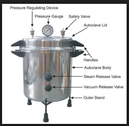
7.0 Equipment Identification

Qualification of utilities and equipment generally includes the following activities:
• Selecting utilities and equipment construction materials, operating principles, and performance characteristics based on whether they are appropriate for their specific uses.
• Verifying that utility systems and equipment are built and installed in compliance with the design specifications (e.g., built as designed with proper materials, capacity, and
functions, and properly connected and calibrated).
• Verifying that utility systems and equipment operate in accordance with the process requirements in all anticipated operating ranges.

Equipment Name

Autoclave

Time controller
¨
2
Pressure controller
¨
2
Temperature controller
¨
3
Pressure gauge
¨
4
Safety Valve
¨
5
Thermometer
¨
Completed By:__________________ Date:_____________

Reviewed By:___________________ Date:_____________

8.0 EQUIPMENT DESCRIPTION

The Autoclave intended to be used for steam sterilizations process. It has following specifications:-

S. No.
Parameter
Range
Readability
Check
01
Timer
0—60 min
1 min
¨
02
Pressure
0—60 Lb/inch²
2.0 Lb/inch²
¨
03
Temperature
0 –150°C
0.5°C
¨
8.1 LOAD IDENTIFICATION

Nature of load
1000ml bottles
Quantity of load
2000 Bottles
8.2 STERILIZATATION CYCLE PARAMETERS
Sterilization set point
106°C
Temperature range
106°C +0.5°C
Expose time
45 minutes

Process Validation Protocol - Pharmaceutical Template PDF PPT XLS

8.3 Equipment Used for PROCESS VALIDATION
Equipment
Calibration
Certificate No.
Issue Date
YES
NO
Recording potentiometer
¨
¨
___________
________
Thermocouples & lead wires
¨
¨
___________
________
Biological indicator i.e.
B. stereothermophyllus
¨
¨
___________
________
Completed By:__________________ Date:_____________

Reviewed By:___________________ Date:_____________

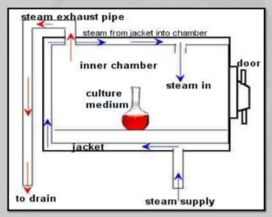
9.0 strerilizatation procedure:

§ Place six thermocouples in the load at the slow to heat points as determined
Previously by(Heat Distribution and Heat Penetration studies)
§ Place thermocouples exterior and near to (Penetration TC)and expose to chamber steam distribution TC)
§ Place BIs (Biological Indicators) at each of the slow to heat penetration location.
§ Load autoclave extend TC out of autoclave and attach to potentiometer
§ Position one TC by controller record sensor
§ Close autoclave door
§ Perform, function check of TC .replace if defective.
§ Replace autoclave sensor chart with a new one
§ Check to make sure that cycle parameters are set
§ Set potentiometer for a 3.0 Hours scan cycle.
§ Initiate sterilization cycle and potentiometer cycle at same time
§ Allow cycle to continue until it is completed. Collect all potentiometers, controls and computer control record and place with protocol.
§ Have computer graph results and calculate Fo value. After load has cooled, remove BIs and have tested
§ Incubate BIs in incubator at 55Cº for 48 hrs

10.0 ACCEPTANCE CRITERIA
1- BDS Strip
All four colors segment of the processed indicator are black. If all other critical process parameters such as temperature, pressure and sterilization are in accordance with cycle reference.
2- Bio-Indicator i.e. B. stereothermophyllus
No growth should be observed after incubation for 48 Hours.
10.1 Results
Temperature : 106°C
Pressure : 10 Lb/inch²
Sterilization Time : 30 minutes
1- Evaluation of the BDS strip.

S.#.
Position of Indicator strip
Stick BDS-test indicator strip on
Acceptance Criteria
Results
All four color segment of indicators strip are black
Yes
No
1
¨
¨

2
¨
¨
2- Evaluation of the Bio-indicator i.e. B. stereothermophyllus

S.#.
Position of
B. stereothermophyllus
Acceptance Criteria
Observation
No growth is observed after incubation for 48 Hours
Yes
No
1
Front/top
left
Fornt/bttm
center
Middle
/centleft
¨
¨

2
Middle/
bttmleft
Rare/top
center
Rare/bttm
left
¨
¨

3
Front/top
center
Front/bottm
center
Middle/cent
left
¨
¨

4
Middle/bttm
right
Rare/top
bottom
Rare/bottm
center
¨
¨

5
Front/top
right
Front/
bottmleft
Middle/
center
¨
¨

6
Middle/
Bttm/Cent
Rare/top
right
Rare/bttm
center
¨
¨
All acceptance criteria have been met. Verified By / Date
Yes ____________No _____________ _____________
If No or N/A, explain in Comments.
Comments:_____________________________________________________________

Completed By:__________________ Date:_____________
Reviewed By:________________ Date:_____________
11.0. Incidents/Deviations

To document any discrepancy or variations noted during the execution of the Process Validation Protocol. Any action to be taken to resolve an outstanding issue is to be identified within the incident report.

INCIDENT #
DESCRIPTION OF INCIDENT
RECORDED BY
DATE

COMMENTS:
____________________________________________________________
____________________________________________________________

12.0 FINAL COMMENTS ABOUT PROCESS VALIDATION
________________________________________________________________
________________________________________________________________
________________________________________________________________
________________________________________________________________

13.0 SIGNATURE IDENTIFICATION SHEET

This sheet is a record of each individual who signs or initials any page included in this protocol or in the attached document. Each person shall be identified by typed or printed name.

Name Signature and Initials Company

__________________ _________________________ _____________________

__________________ _________________________ _____________________

__________________ _________________________ _____________________

__________________ _________________________ _____________________

__________________ _________________________ _____________________

__________________ ________________________ _____________________

__________________ ________________________ _____________________

__________________ ________________________ _____________________

__________________ _________________________ _____________________
FINAL APPROVAL OF QUALIFICATION
This document certifies that the process of Autoclavation has been validated as specified and complies with Standard Operating Procedures, and satisfies the requirements for cGMPs.
Name & Designation
Signature
Date
Prepared By

Tahir Ibrahim
Quality Assurance Executive

checked and Reviewed By

Abdul Hafeez
Production manager
Approved By
Tajjamal A Qurashi
Manager Quality Control
PROTOCOL TRAINING
Training Session Date : ____________________
Instructor : ____________________
Protocol Reference : ____________________

Name
Title
Signature
Date

PROCESS VALIDATION PROTOCOL -Pharmaceutical Template PDF PPT XLS
In conclusion, there is far to think about about your Computer System Validation system last to a strong inspection. Make every effort to have a system stock list put in place, the appropriate SOPs in place, and additionally to check the critical techniques and their documentation just before a powerful FDA inspection. Again, simply because the FDA can be inspecting the institution for other factors, doesn’t discount the potential the couple need to audit your pc System Validation School. As mentioned, so many of our businesses respective company procedures are carried out by way of electronic systems in this young age of technologies. Therefore, it could be useful to evaluate the Computer Validation Program whether you foresee a strong inspection or otherwise not. Having a powerful efficient Computer System Validation System put in place will help ensure the stability of the electronic documents, allocate resources better and subsequently can yield long run cost discounts to the company.
more information

DOCUMENTATION

Documentation at each stage of the process validation lifecycle is essential for effective communication in complex, lengthy, and multidisciplinary projects. Documentation is important
so that knowledge gained about a product and process is accessible and comprehensible to others involved in each stage of the lifecycle. Information transparency and accessibility are
fundamental tenets of the scientific method. They are also essential to enabling organizational units responsible and accountable for the process to make informed, science-based decisions that
ultimately support the release of a product to commerce.
The degree and type of documentation required by CGMP vary during the validation lifecycle. Documentation requirements are greatest during Stage 2, process qualification, and Stage 3,
continued process verification. Studies during these stages must conform to CGMPs and must be approved by the quality unit in accordance with the regulations .
Viral and impurity clearance studies, even when performed at small scale, also require quality
unit oversight.
CGMP documents for commercial manufacturing (i.e., the initial commercial master batch production and control record and supporting procedures) are key outputs of Stage 1,
process design. We recommend that firms diagram the process flow for the full-scale process.
Process flow diagrams should describe each unit operation, its placement in the overall process, monitoring and control points, and the component, as well as other processing material inputs
(e.g., processing aids) and expected outputs (i.e., in-process materials and finished product). It is also useful to generate and preserve process flow diagrams of the various scales as the process
design progresses to facilitate comparison and decision making about their comparability.

In conclusion, there is far to think about about your Computer System Validation system last to a strong inspection just before a powerful FDA inspection. Again, simply because the FDA can be inspecting the institution for other factors, doesn’t discount the potential the couple need to audit your pc System Validation School. As mentioned, so many of our businesses respective company procedures are carried out by way of electronic systems in this young age of technologies. Therefore, it could be useful to evaluate the Computer Validation Program whether you foresee a strong inspection or otherwise not.

GLOSSARY OF TERMS

2.1 List of Abbreviation

CGMP Current Good Manufacturing Practices
FDA Food and Drug Administration
GAMP Good Automated Manufacturing Practice
GMP Good Manufacturing Practice
IQ Installation Qualification
OQ Operation Qualification

2.2 Definitions

Acceptance Criteria Agreed standards or ranges, which must be achieved.
Critical component A component within a system where the operation, contact, data, control, alarm, or failure may have a direct impact on the quality of the product.
Critical Instrument Any instrument that directly affects product safety, purity, or efficacy.
Direct Impact System An engineering system that may have a direct impact on product quality.
Factor Acceptance Test Documenting the performance characteristics of equipment prior to shipment to site.
Impact Assessment The process of evaluating the impact of the operating, controlling alarming and failure conditions of a system on the quality of a product.
Indirect Impact System An engineering system considered not having a direct impact on product quality.
Installation Qualification Documenting the process equipment and ancillary system are constructed and installed according to pre-determined specifications and functional requirements.
No Impact System This is a system that will not have any impact, either directly or indirectly, on product quality. These systems are designed and commissioned following Good engineering Practice only.
Non-critical Component A component within a system where the operation, contact, alarm or failure may have an indirect impact or no impact on the quality of product.
Operating Limits The minimum and /or maximum values that will ensure that product and safety requirements are met.
Operational Qualification Establishing confidence that process equipment and ancillary systems are capable of consistently operating within established limits and tolerances.
Performance Qualification The documented verification that al aspects of a facility, utility or equipment that can affect product quality perform as intended meeting pre-determined acceptance criteria.
Performance Testing The process by which the performance of interdependent system is demonstrated as within the required tolerances, the output of interdependent system is demonstrated as delivering the required duty or capacity, the interdependent functions of system are interdependent to be as specified and appropriate.
Piping and Instrumentation
Diagrams Primary source of design information for utility systems and process equipment. They are used to depict the process flow, equipment configuration, process parameters, instrumentation, and materials of construction. They also are used to perform overall material and energy balances and pressure balances.

Capability of a process: Ability of a process to produce a product that will fulfill the requirements of that product. The concept of process capability can also be defined in statistical terms. (ISO 9000:2005)

Commercial manufacturing process: The manufacturing process resulting in commercial product (i.e., drug that is marketed, distributed, and sold or intended to be sold). For the purposes of this guidance, the term commercial manufacturing process does not include clinical trial or treatment IND material.

Concurrent release: Releasing for distribution a lot of finished product, manufactured following a qualification protocol, that meets the lot release criteria established in the protocol, but before the entire study protocol has been executed.

Continued process verification: Assuring that during routine production the process remains in a state of control. Performance indicators: Measurable values used to quantify quality objectives to reflect the performance of an organization, process or system, also known as performance metrics in some regions. (ICH Q10)

Process design: Defining the commercial manufacturing process based on knowledge gained through development and scale-up activities.

Process qualification: Confirming that the manufacturing process as designed is capable of reproducible commercial manufacturing.

Process validation: The collection and evaluation of data, from the process design stage through commercial production, which establishes scientific evidence that a process is capable of consistently delivering quality products.

Quality: The degree to which a set of inherent properties of a product, system, or process fulfils requirements. (ICH Q9)

State of control: A condition in which the set of controls consistently provides assurance of continued process performance and product quality. (ICH Q10)

Autoclave Sterilization Principle & Working PDF PPT – Autoclave Validation – Autoclave Diagram

Autoclave Sterilization Principle & Working Diagram

Autoclave Sterilization: Autoclaves provide a physical method for disinfection and sterilization. They work with a combination of steam, pressure and time. Autoclaves operate at high temperature and pressure in order to kill microorganisms and spores.

Autoclave Sterilization

Autoclave Sterilizers are used to decontaminate certain biological waste and sterilize media, instruments and lab ware. Regulated medical waste that might contain bacteria, viruses and other biological material are recommended to be inactivated by autoclaving before disposal.

An autoclave is used to sterilize surgical equipment, laboratory instruments, pharmaceutical items, and other materials. It can sterilize solids, liquids, hollows, and instruments of various shapes and sizes. Autoclaves vary in size, shape and functionality. A very basic autoclave is similar to a pressure cooker; both use the power of steam to kill bacteria, spores and germs resistant to boiling water and powerful detergents.

Do you want to do CANADIAN Masters Degree & Ph.D in Pharmacy under Canadian Universities

Banned drugs news 2018: Latest News on sale of 3 Banned drugs

List of Banned Drugs  – PDF Full Download – 2018 – Latest News

Autoclave Sterilizers:

To be effective against spore forming bacteria and viruses, autoclaves need to have steam in direct contact with the material being sterilized (i.e. loading of items is very important).

Create vacuum in order to displace all the air initially present in the autoclave and replacing it with steam.

Implement a well designed control scheme for steam evacuation and cooling so that the load does not perish.

The efficiency of the sterilization process depends on two major factors. One of them is the thermal death time, i.e. the time microbes must be exposed to at a particular temperature before they are all dead. The second factor is the thermal death point or temperature at which all microbes in a sample are killed.

The steam and pressure ensure sufficient heat is transferred into the organism to kill them. A series of negative pressure pulses are used to vacuum all possible air pockets, while steam penetration is maximized by application of a succession of positive pulses

Autoclave Sterilization Principle & Working PDF PPT - Autoclave Validation - Autoclave Diagram

Autoclave Uses & Advantages:

An autoclave chamber sterilizes medical or laboratory instruments by heating them above boiling point. Most clinics have tabletop autoclaves, similar in size to microwave ovens. Hospitals use large autoclaves, also called horizontal autoclaves. They’re usually located in the the Central Sterile Services Department CSSD) and can process numerous surgical instruments in a single sterilization cycle, meeting the ongoing demand for sterile equipment in operating rooms and emergency wards.

They are important in tattoo shops, beauty and barber shops, dentist offices, veterinarians and many other fields.

Autoclave disadvantages:

Autoclave is unsuitable for heat sensitive objects.

Autoclaves Working Principle:

Autoclaves use pressurized steam as their sterilization agent. The basic concept of an autoclave is to have each item sterilized -whether it is a liquid, plastic ware, or glassware- come in direct contact with steam at a specific temperature and pressure for a specific amount of time. Time, steam, temperature, and pressure are the four main parameters required for a successful sterilization using an autoclave.

The amount of time and temperature required for sterilization depends on the type of material being autoclaved. Using higher temperatures for sterilization requires shorter times. The most common temperatures used are 121 C and 132 C. In order for steam to reach these high temperatures, steam has to be pumped into the chamber at a pressure higher than normal atmospheric pressure.

Now that we have covered the basic principle of how autoclaves use pressurized steam to sterilize contaminated materials, we will now go over how autoclaves operate.

Autoclave Design Diagram & Parts

Autoclave Sterilization Principle & Working Diagram

Similar to pressure cookers, steam sterilizer autoclaves work quickly and effectively because of their high temperature. The machine’s temperature and unique shape make it easier to hold the heat inside much longer. The autoclave also does a great job of efficiently penetrating each piece of equipment. The autoclave’s chambers are usually in the shape of a cylinder because cylindrical shapes are more equipped to handle the high pressure that is needed for the sterilization process to work. For safety reasons, there is an outside lock and a safety valve that prevents the autoclave steam sterilizer’s pressure from getting too high.

Once you close the autoclave sterilizer chamber, a vacuum pump removes all the air from inside the device or it is forced out by pumping in steam. If done the first way, the sterilizer is pumped with high pressured steam to quickly raise the internal temperature. On every autoclave there is a thermometer that is waiting for the thermal sweet point, 268-273 degrees Fahrenheit, and then it starts its timer. During the sterilizing process, steam is continuously entering the autoclave to thoroughly kill all dangerous microorganisms. Once the required time of sterilization has the elapsed, the chamber will be exhausted of pressure and steam allowing the door to open for cooling and drying of the contents.

Mode of Action Autoclave Sterilizers:

Moist heat destroys microorganisms by the irreversible coagulation and denaturation of enzymes and structural proteins. In support of this fact, it has been found that the presence of moisture significantly affects the coagulation temperature of proteins and the temperature at which microorganisms are destroyed.

Autoclave Working – Operation:

Place containers in the autoclave.

Check the strainer to see if it is clogged. The strainer is located on the bottom of the chamber near the door. The autoclave will not come up to pressure if the strainer is clogged.

Close door.

               For the SMALL autoclave, rotate the handle clockwise until it is snugly closed.     

                For the LARGE autoclave, rotate the small, inner handle clockwise first until it locks. Then rotate the large outer handle clockwise until it is snug.

Open the glass-faced door in the upper right corner. Set STERILIZE time and, if needed, set DRY time.

Select the SETTING you want by pushing in the colored button that corresponds to:

ON-OFF                FAST EXHAUST  FLUIDS  DRY

GREEN= FAST EXHAUST:  Pressure will decrease rapidly at the end of sterilization. Fluids will bubble over if you use this setting.

YELLOW= Fluids: Pressure decreases more slowly at the end of sterilization.

BLUE=Dry:  Use this setting for paper goods, cotton swabs, etc.

Push in the RED button to turn the autoclave on.

Wait until the temperature reaches 121°C and the RED sterilization light in the glass-faced box turns on before recording the Chamber Pressure on the Log. The chamber pressure should be 16-20 psi once the sterilization cycle starts. Anything below 16 psi should be reported to your lab manager.

At the end of the run, insure the CHAMBER PRESSURE has returned to ZERO before attempting to open the door. The FLUIDS cycle takes much longer than FAST EXHAUST – be patient. If the door cannot be easily opened, WAIT 10 minutes before trying again. If you wrench on the door and  attempt to force it open, the internal metal rod that connects to the door handle will twist from the pressure.

To open the door:

SMALL autoclave: rotate the handle counterclockwise. Be careful, steam burns!  Step to the side and crack open the door. Allow the steam to escape from the chamber then open the door and remove your items.

LARGE autoclave: First rotate the LARGE OUTER handle counterclockwise until it is loose. Next, rotate the SMALL INNER handle counterclockwise until the door opens. Be careful, steam burns!  Step to the side and crack open the door. Allow the steam to escape from the chamber then open the door and remove your items.

As a courtesy to others needing to use the autoclave, promptly remove your items when the cycle is completed and you can easily open the door. Wear protective, heat resistant gloves when removing items.

Autoclaved waste materials are to be taken directly to the dumpster for disposal. Orange autoclave bags must be put into black trash bags before disposing in the dumpster.

Autoclave Cycles

To be effective, the autoclave must reach and maintain a temperature of 121° C for at least 30 minutes by using saturated steam under at least 15 psi of pressure. Increased cycle time may be necessary depending upon the make-up and volume of the load.

The rate of exhaust will depend upon the nature of the load. Dry material can be treated in a fast exhaust cycle, while liquids and biological waste require slow exhaust to prevent boiling over of super-heated liquids.

Liquids cycle

 Liquids rely on the Liquids Cycle to avoid a phenomenon known as “boil-over.” Boil-over is simply a liquid boiling so violently that it spills over the top of its container.  Boil-over will occur if the pressure in your autoclave chamber is released too quickly during the exhaust phase of the cycle.  Significant liquid volume can be lost to boil-over, and this can result in unwanted spills on the bottom of the autoclave chamber that must be cleaned up to avoid clogging the drain lines and the subsequent repair costs to the department.

To help prevent boil-over during the exhaust phase, the chamber pressure must be released slowly.  This process is controlled by the sterilizer’s control system. Controlling the exhaust rate allows the liquid load to cool off as the surrounding chamber pressure is decreased.

The exhaust rate for a Liquids Cycle is different from a standard Gravity or Vacuum Cycle, where the chamber pressure is released quickly. To prevent boil-over, the chamber pressure must decrease slowly to allow the temperature of the load to remain below the boiling point.  If the pressure is exhausted all at once, the temperature of the load will be above its boiling point, resulting in instant and violent boiling.

(Slow Exhaust)

Material Recommended for:

Use with glass containers with vented closures; 2/3 full only

  • Liquid media
  • Nonflammable liquids
  • Aqueous solutions
  • Liquid biological waste

Solids or Dry cycle

(Fast Exhaust)

Material Recommended for:

Glassware: empty and inverted

no tight or impermeable closures

Dry hard items, either unwrapped or in porous wrap

Metal items with porous parts

Other porous materials

Gravity Cycle: Wrapped Goods or Pre vacuum cycle

(Clean: Fast Exhaust

Dirty: Slow Exhaust)

The traditional “Gravity Cycle” is the most common and simplest steam sterilization cycle. During a Gravity Cycle, steam is pumped into a chamber containing ambient air. Because steam has a lower density than air, it rises to the top of the chamber and eventually displaces all the air. As steam fills the chamber, the air is forced out through a drain vent. By pushing the air out, the steam is able to directly contact the load and begin to sterilize it.

At the end of the cycle, the steam is discharged through the drain vent. However, the load can still be hot and possibly wet. To address this issue, gravity autoclaves can be equipped with a post-cycle vacuum feature to assist in drying the load. The sterilizer runs a normal Gravity Cycle and after the load is sterilized, a vacuum pulls steam and condensation through the drain vent. The longer the vacuum system runs during the dry phase, the cooler and dryer the goods will be when removed from the chamber.

Gravity Cycles are commonly used on loads like glassware, bio-hazardous waste (autoclave bag waste), and wrapped and unwrapped instruments.

Material Recommended for:

Glassware that must be sterilized upright and/or can trap air

Wrapped dry items that can trap air

Pipette tip boxes

Sharps decontamination

(in collection containers)

Biohazard waste decontamination, in autoclave bags; can be wet or dry

Autoclave Types & Market

  • Medical autoclaves
  • Dental autoclaves
  • Laboratory autoclaves

Medical autoclaves

Tabletop autoclaves
large horizontal autoclaves
Plasma Sterilizer
Washer Disinfectors
Autoclaves maintain a healthy, clean and sterile environment.
Fast and effective disinfection of surgical instruments in preparation for sterilization is ensured by Autoclaves.
Autoclaves that satisfy the needs of any hospital operating room, central sterile services department or medical clinic.

Dental autoclaves

– ideal sterilizer for dentists

Laboratory autoclaves 

vertical loading autoclaves and fast liquid cooling autoclaves

Life science labs and research institutes need sterilization techniques inevitably

Autoclave Validation

Chemical Indicators

Tape Indicators

Tape indicators are adhesive-backed paper tape with heat sensitive, chemical indicator markings.  Tape indicators change color or display diagonal stripes, the words “sterile” or “autoclaved” when exposed to temperatures of 121°C.  Tape indicators are typically placed on the exterior of the waste load.  If the temperature sensitive tape does not indicate that a temperature of at least 121°C was reached during the sterilization process, the load is not considered decontaminated.   If tape indicators fail on two consecutive loads, notify your Department Safety Manager.

Tape indicators are not designed nor intended to prove that organisms have actually been killed. They indicate that a temperature of 121°C has been achieved within the autoclave.  EHS recommends that you DO NOT use autoclave tape as the only indicator of decontamination or sterilization.

Integrated Chemical Indicator Strips

Integrated chemical indicator strips provide a limited validation of temperature and time by displaying a color change after exposure to  normal autoclave operating temperatures of 121ºC for several minutes.  Chemical color change indicators can be placed within the waste load.  If the chemical indicators fail on two consecutive loads, notify your Department Safety Manager.                            

Biological Indicators

Biological indicator vials contain spores from B. stearothermophilus, a microorganism that is inactivated when exposed to 121.1oC saturated steam for a minimum of 20 minutes. Autoclaves used to treat biological waste will be evaluated with a biological indicator by EHS on a quarterly basis.

Validation Procedure for Autoclave:

EHS will coordinate biological validation testing with laboratory staff.

The indicators will be incubated by EHS for 24 hours at 60°C with a control that has been maintained at room temperature.

Results

If the autoclaved indicator exhibits growth, the validation has failed and will be repeated.

If the second validation indicator fails, EHS will notify the Department Safety Manager and request service on the autoclave.  Autoclave should not be used until service has been conducted and the validation test passes.

Validation tests results are emailed by EHS staff to the appropriate labs and the Department Safety Manager.

EHS maintains documentation of all validation tests.

Autoclave Principle , Principle Of Autoclave , Working Principle Of Autoclave , Autoclave Principle Of Operation , Working Ggg Principle Of Autoclave , Autoclave Working Principle , Autoclave Principle And Working , Autoclaving Principle , Application Of Autoclave , Autoclave Working , Autoclave Principle Of Operation , Working Of Autoclave , Autoclave Application, Principle Of Autoclave Sterilization, Working Principle Of Autoclave , Working Principle Of Autoclave , Autoclave Principle And Procedure, Autoclave Working Principle, Autoclave Principle And Working,

[PPT PDF] Pharmaceutical Water System Design Validation -SAMPLING CONSIDERATIONS

[PPT PDF] Pharmaceutical Water System Design Validation -SAMPLING CONSIDERATIONS

Pharmaceutical Water System- SAMPLING CONSIDERATIONS

Water systems should be monitored at a frequency that is sufficient to ensure that the system is in control and continues to produce water of acceptable quality. Samples should be taken from representative locations within the processing and distribution system. Established sampling frequencies should be based on system validation data and should cover critical areas including unit operation sites. The sampling plan should take into consideration the desired attributes of the water being sampled. For example, systems for Water for Injection because of their more critical microbiological requirements, may require a more rigorous sampling frequency.

Analyses of water samples often serve two purposes: in-process control assessments and final quality control assessments. In-process control analyses are usually focused on the attributes of the water within the system. Quality control is primarily concerned with the attributes of the water delivered by the system to its various uses. The latter usually employs some sort of transfer device, often a flexible hose, to bridge the gap between the distribution system use-point valve and the actual location of water use. The issue of sample collection location and sampling procedure is often hotly debated because of the typically mixed use of the data generated from the samples, for both in-process control and quality control. In these single sample and mixed data use situations, the worst-case scenario should be utilized. In other words, samples should be collected from use points using the same delivery devices, such as hoses, and procedures, such as preliminary hose or outlet flushing, as are employed by production from those use points. Where use points per se cannot be sampled, such as hard-piped connections to equipment, special sampling ports may be used. In all cases, the sample must represent as closely as possible the quality of the water used in production. If a point of use filter is employed, sampling of the water prior to and after the filter is needed because the filter will mask the microbial control achieved by the normal operating procedures of the system.

Samples containing chemical sanitizing agents require neutralization prior to microbiological analysis. Samples for microbiological analysis should be tested immediately, or suitably refrigerated to preserve the original microbial attributes until analysis can begin. Samples of flowing water are only indicative of the concentration of planktonic (free floating) microorganisms present in the system. Biofilm microorganisms (those attached to water system surfaces) are usually present in greater numbers and are the source of the planktonic population recovered from grab samples. Microorganisms in biofilms represent a continuous source of contamination and are difficult to directly sample and quantify. Consequently, the planktonic population is usually used as an indicator of system contamination levels and is the basis for system Alert and Action Levels. The consistent appearance of elevated planktonic levels is usually an indication of advanced biofilm development in need of remedial control. System control and sanitization are key in controlling biofilm formation and the consequent planktonic population.

Sampling for chemical analyses is also done for in-process control and for quality control purposes. However, unlike microbial analyses, chemical analyses can be and often are performed using on-line instrumentation. Such on-line testing has unequivocal in-process control purposes because it is not performed on the water delivered from the system. However, unlike microbial attributes, chemical attributes are usually not significantly degraded by hoses. Therefore, through verification testing, it may be possible to show that the chemical attributes detected by the on-line instrumentation (in-process testing) are equivalent to those detected at the ends of the use point hoses (quality control testing). This again creates a single sample and mixed data use scenario. It is far better to operate the instrumentation in a continuous mode, generating large volumes of in-process data, but only using a defined small sampling of that data for QC purposes. Examples of acceptable approaches include using highest values for a given period, highest time-weighted average for a given period (from fixed or rolling sub-periods), or values at a fixed daily time. Each approach has advantages and disadvantages relative to calculation complexity and reflection of continuous quality, so the user must decide which approach is most suitable or justifiable.

Pharmaceutical Water System-CHEMICAL CONSIDERATIONS

The chemical attributes of Purified Water and Water for Injection were specified by a series of chemistry tests for various specific and nonspecific attributes with the intent of detecting chemical species indicative of incomplete or inadequate purification. While these methods could have been considered barely adequate to control the quality of these waters, they nevertheless stood the test of time. This was partly because the operation of water systems was, and still is, based on on-line conductivity measurements and specifications generally thought to preclude the failure of these archaic chemistry attribute tests.

USP moved away from these chemical attribute tests to contemporary analytical technologies for the bulk waters Purified Water and Water for Injection. The intent was to upgrade the analytical technologies without tightening the quality requirements. The two contemporary analytical technologies employed were TOC and conductivity. The TOC test replaced the test for Oxidizable substances that primarily targeted organic contaminants. A multistaged Conductivity test which detects ionic (mostly inorganic) contaminants replaced, with the exception of the test for Heavy metals, all of the inorganic chemical tests (i.e., Ammonia, Calcium, Carbon dioxide, Chloride, Sulfate).

Pharmaceutical Water Systems: Pharmaceutical Water Storage & Distribution Systems

Replacing the heavy metals attribute was considered unnecessary because (a) the source water specifications (found in the NPDWR) for individual Heavy metals were tighter than the approximate limit of detection of the Heavy metals test for USP XXII Water for Injection and Purified Water (approximately 0.1 ppm), (b) contemporary water system construction materials do not leach heavy metal contaminants, and (c) test results for this attribute have uniformly been negative—there has not been a confirmed occurrence of a singular test failure (failure of only the Heavy metals test with all other attributes passing) since the current heavy metal drinking water standards have been in place. Nevertheless, since the presence of heavy metals in Purified Water or Water for Injection could have dire consequences, its absence should at least be documented during new water system commissioning and validation or through prior test results records.

Total solids and pH are the only tests not covered by conductivity testing. The test for Total solids was considered redundant because the nonselective tests of conductivity and TOC could detect most chemical species other than silica, which could remain undetected in its colloidal form. Colloidal silica in Purified Water and Water for Injection is easily removed by most water pretreatment steps and even if present in the water, constitutes no medical or functional hazard except under extreme and rare situations. In such extreme situations, other attribute extremes are also likely to be detected. It is, however, the user’s responsibility to ensure fitness for use. If silica is a significant component in the source water, and the purification unit operations could be operated or fail and selectively allow silica to be released into the finished water (in the absence of co-contaminants detectable by conductivity), then either silica-specific or a total solids type testing should be utilized to monitor and control this rare problem.

The pH attribute was eventually recognized to be redundant to the conductivity test (which included pH as an aspect of the test and specification); therefore, pH was dropped as a separate attribute test.

The rationale used by USP to establish its conductivity specification took into consideration the conductivity contributed by the two least conductive former attributes of Chloride and Ammonia, thereby precluding their failure had those wet chemistry tests been performed. In essence, the Stage 3 conductivity specifications (see Water Conductivity  645 ) were established from the sum of the conductivities of the limit concentrations of chloride ions (from pH 5.0 to 6.2) and ammonia ions (from pH 6.3 to 7.0), plus the unavoidable contribution of other conductivity-contributing ions from water (H+ and OH–), dissolved atmospheric CO2 (as HCO3–), and an electro-balancing quantity of either Na+ of Cl–, depending on the pH-induced ionic imbalance (see Table 1). The Stage 2 conductivity specification is the lowest value on this table, 2.1 µS/cm. The Stage 1 specifications, designed primarily for on-line measurements, were derived essentially by summing the lowest values in the contributing ion columns for each of a series of tables similar to Table 1, created for each 5  increment between 0  and 100 . For example purposes, the italicized values in Table 1, the conductivity data table for 25 , were summed to yield a conservative value of 1.3 µS/cm, the Stage 1 specification for a nontemperature compensated, nonatmosphere equilibrated water sample that actual had a measured temperature of 25  to 29 . Each 5  increment table was similarly treated to yield the individual values listed in the table of Stage 1 specifications (see Water Conductivity  645 ).

As stated above, this rather radical change to utilizing a conductivity attribute as well as the inclusion of a TOC attribute allowed for on-line measurements. This was a major philosophical change and allowed major savings to be realized by industry. The TOC and conductivity tests can also be performed “off-line” in the laboratories using collected samples, though sample collection tends to introduce opportunities for adventitious contamination that can cause false high readings. The collection of on-line data is not, however, without challenges. The continuous readings tend to create voluminous amounts of data where before only a single data point was available. As stated under Sampling Considerations, continuous in-process data is excellent for understanding how a water system performs during all of its various usage and maintenance events in real time, but is too much data for QC purposes. Therefore, a justifiable fraction or averaging of the data can be used that is still representative of the overall water quality being used.

Packaged waters present a particular dilemma relative to the attributes of conductivity and TOC. The package itself is the source of chemicals (inorganics and organics) that leach over time into the water and can easily be detected. The irony of organic leaching from plastic packaging is that when the Oxidizable substances test was the only “organic contaminant” test for both bulk and packaged waters, that test’s insensitivity to those organic leachables rendered their presence in packaged water at high concentrations (many times the TOC specification for bulk water) virtually undetectable. Similarly, glass containers can also leach inorganics, such as sodium, which are easily detected by conductivity, but are undetected by the wet chemistry tests for water (other than pH or Total solids). Most of these leachables are considered harmless by current perceptions and standards at the rather significant concentrations present. Nevertheless, they effectively degrade the quality of the high-purity waters placed into these packaging system. Some packaging materials contain more leachables than others and may not be as suitable for holding water and maintaining its purity.

The attributes of conductivity and TOC tend to reveal more about the packaging leachables than they do about the water’s original purity. These “allowed” leachables could render the packaged versions of originally equivalent bulk water essentially unsuitable for many uses where the bulk waters are perfectly adequate.

[PPT PDF] Pharmaceutical Water System Design Validation -SAMPLING CONSIDERATIONS pdf [PPT PDF] Pharmaceutical Water System Design Validation -SAMPLING CONSIDERATIONS

Pharmaceutical Water System-MICROBIAL CONSIDERATIONS

The major exogenous source of microbial contamination of bulk pharmaceutical water is source or feed water. Feed water quality must, at a minimum, meet the quality attributes of Drinking Water for which the level of coliforms are regulated. A wide variety of other microorganisms, chiefly Gram-negative bacteria, may be present in the incoming water. These microorganisms may compromise subsequent purification steps. Examples of other potential exogenous sources of microbial contamination include unprotected vents, faulty air filters, ruptured rupture disks, backflow from contaminated outlets, unsanitized distribution system “openings” including routine component replacements, inspections, repairs, and expansions, inadequate drain and air-breaks, and replacement activated carbon, deionizer resins, and regenerant chemicals. In these situations, the exogenous contaminants may not be normal aquatic bacteria but rather microorganisms of soil or even human origin. The detection of nonaquatic microorganisms may be an indication of a system component failure, which should trigger investigations that will remediate their source. Sufficient care should be given to system design and maintenance in order to minimize microbial contamination from these exogenous sources.

Unit operations can be a major source of endogenous microbial contamination. Microorganisms present in feed water may adsorb to carbon bed, deionizer resins, filter membranes, and other unit operation surfaces and initiate the formation of a biofilm. In a high-purity water system, biofilm is an adaptive response by certain microorganisms to survive in this low nutrient environment. Downstream colonization can occur when microorganisms are shed from existing biofilm-colonized surfaces and carried to other areas of the water system. Microorganisms may also attach to suspended particles such as carbon bed fines or fractured resin particles. When the microorganisms become planktonic, they serve as a source of contamination to subsequent purification equipment (compromising its functionality) and to distribution systems.

Another source of endogenous microbial contamination is the distribution system itself. Microorganisms can colonize pipe surfaces, rough welds, badly aligned flanges, valves, and unidentified dead legs, where they proliferate, forming a biofilm. The smoothness and composition of the surface may affect the rate of initial microbial adsorption, but once adsorbed, biofilm development, unless otherwise inhibited by sanitizing conditions, will occur regardless of the surface. Once formed, the biofilm becomes a continuous source of microbial contamination.

[PPT PDF] Pharmaceutical Water System Design Validation -SAMPLING CONSIDERATIONS

ENDOTOXIN CONSIDERATIONS

Endotoxins are lipopolysaccharides found in and shed from the cell envelope that is external to the cell wall of Gram-negative bacteria. Gram-negative bacteria that form biofilms can become a source of endotoxins in pharmaceutical waters. Endotoxins may occur as clusters of lipopolysaccharide molecules associated with living microorganisms, fragments of dead microorganisms or the polysaccharide slime surrounding biofilm bacteria, or as free molecules. The free form of endotoxins may be released from cell surfaces of the bacteria that colonize the water system, or from the feed water that may enter the water system. Because of the multiplicity of endotoxin sources in a water system, endotoxin quantitation in a water system is not a good indicator of the level of biofilm abundance within a water system.

Pharmaceutical Water System Design Validation – Microbial Testing of Water

Endotoxin levels may be minimized by controlling the introduction of free endotoxins and microorganisms in the feed water and minimizing microbial proliferation in the system. This may be accomplished through the normal exclusion or removal action afforded by various unit operations within the treatment system as well as through system sanitization. Other control methods include the use of ultrafilters or charge-modified filters, either in-line or at the point of use. The presence of endotoxins may be monitored as described in the general test chapter Bacterial Endotoxins Test  85 .

MICROBIAL ENUMERATION CONSIDERATIONS

The objective of a water system microbiological monitoring program is to provide sufficient information to control and assess the microbiological quality of the water produced. Product quality requirements should dictate water quality specifications. An appropriate level of control may be maintained by using data trending techniques and, if necessary, limiting specific contraindicated microorganisms. Consequently, it may not be necessary to detect all of the microorganisms species present in a given sample. The monitoring program and methodology should indicate adverse trends and detect microorganisms that are potentially harmful to the finished product, process, or consumer. Final selection of method variables should be based on the individual requirements of the system being monitored.

It should be recognized that there is no single method that is capable of detecting all of the potential microbial contaminants of a water system. The methods used for microbial monitoring should be capable of isolating the numbers and types of organisms that have been deemed significant relative to in-process system control and product impact for each individual system. Several criteria should be considered when selecting a method to monitor the microbial content of a pharmaceutical water system. These include method sensitivity, range of organisms types or species recovered, sample processing throughput, incubation period, cost, and methodological complexity. An alternative consideration to the use of the classical “culture” approaches is a sophisticated instrumental or rapid test method that may yield more timely results. However, care must be exercised in selecting such an alternative approach to ensure that it has both sensitivity and correlation to classical culture approaches, which are generally considered the accepted standards for microbial enumeration.

Pharmaceutical Water System Design Operation & Validation

Consideration should also be given to the timeliness of microbial enumeration testing after sample collection. The number of detectable planktonic bacteria in a sample collected in a scrupulously clean sample container will usually drop as time passes. The planktonic bacteria within the sample will tend to either die or to irretrievably adsorb to the container walls reducing the number of viable planktonic bacteria that can be withdrawn from the sample for testing. The opposite effect can also occur if the sample container is not scrupulously clean and contains a low concentration of some microbial nutrient that could promote microbial growth within the sample container. Because the number of recoverable bacteria in a sample can change positively or negatively over time after sample collection, it is best to test the samples as soon as possible after being collected. If it is not possible to test the sample within about 2 hours of collection, the sample should be held at refrigerated temperatures (2  to 8 ) for a maximum of about 12 hours to maintain the microbial attributes until analysis. In situations where even this is not possible (such as when using off-site contract laboratories), testing of these refrigerated samples should be performed within 48 hours after sample collection. In the delayed testing scenario, the recovered microbial levels may not be the same as would have been recovered had the testing been performed shortly after sample collection. Therefore, studies should be performed to determine the existence and acceptability of potential microbial enumeration aberrations caused by protracted testing delays.

Source : USP

Expert Committee : (PW05) Pharmaceutical Waters 05

USP29–NF24 Page 3056

Pharmacopeial Forum : Volume No. 30(5) Page 1744

Pharmaceutical Water System Ppt,

Pharmaceutical Water Systems,

Purified Water Specification As Per Usp,

Pharmaceutical Water System Design Operation And Validation Pdf,

pharmaceutical water system design operation and validation,

pharmaceutical water system ppt – What is Pharmaceutical water,

purified water & Water for Injection SOP as per usp,

Pharmaceutical Water Systems: Storage & Distribution Systems,

pharmaceutical water system : Inspection of Pharmaceutical water systems,

pharmaceutical water Production : Water purification systems,

Pharmaceutical Water Systems: Types: Water quality specifications,

Pharmaceutical Water System: principles for pharmaceutical water systems

Pharmaceutical Water System Design Operation & Validation Pdf PowerPoint

PPT PDF Pharmaceutical Water System Validation Pdf PowerPoint

VALIDATION AND QUALIFICATION OF WATER PURIFICATION, STORAGE, AND DISTRIBUTION SYSTEMS: Establishing the dependability of pharmaceutical water purification, storage, and distribution systems requires an appropriate period of monitoring and observation. Ordinarily, few problems are encountered in maintaining the chemical purity of Purified Water and Water for Injection Nevertheless, the advent of using conductivity and TOC to define chemical purity has allowed the user to more quantitatively assess the water’s chemical purity and its variability as a function of routine pretreatment system maintenance and regeneration. Even the presence of such unit operations as heat exchangers and use point hoses can compromise the chemical quality of water within and delivered from an otherwise well-controlled water system. Therefore, an assessment of the consistency of the water’s chemical purity over time must be part of the validation program. However, even with the most well controlled chemical quality, it is often more difficult to consistently meet established microbiological quality criteria owing to phenomena occurring during and after chemical purification. A typical program involves intensive daily sampling and testing of major process points for at least one month after operational criteria have been established for each unit operation, point of use, and sampling point.

VALIDATION AND QUALIFICATION OF WATER PURIFICATION, STORAGE, AND DISTRIBUTION SYSTEMS

An overlooked aspect of water system validation is the delivery of the water to its actual location of use. If this transfer process from the distribution system outlets to the water use locations (usually with hoses) is defined as outside the water system, then this transfer process still needs to be validated to not adversely affect the quality of the water to the extent it becomes unfit for use. Because routine microbial monitoring is performed for the same transfer process and components (e.g., hoses and heat exchangers) as that of routine water use (see Sampling Considerations), there is some logic to include this water transfer process within the distribution system validation.

Validation is the process whereby substantiation to a high level of assurance that a specific process will consistently produce a product conforming to an established set of quality attributes is acquired and documented. Prior to and during the very early stages of validation, the critical process parameters and their operating ranges are established. A validation program qualifies and documents the design, installation, operation, and performance of equipment. It begins when the system is defined and moves through several stages: installation qualification (IQ), operational qualification (OQ), and performance qualification (PQ). A graphical representation of a typical water system validation life cycle is shown in Figure.

PPT PDF Pharmaceutical Water System Validation Pdf PowerPoint

Pharmaceutical Water system validation life cycle.

A validation plan for a water system typically includes the following steps: (1) establishing standards for quality attributes of the finished water and the source water; (2) defining suitable unit operations and their operating parameters for achieving the desired finished water quality attributes from the available source water; (3) selecting piping, equipment, controls, and monitoring technologies; (4) developing an IQ stage consisting of instrument calibrations, inspections to verify that the drawings accurately depict the final configuration of the water system and, where necessary, special tests to verify that the installation meets the design requirements; (5) developing an OQ stage consisting of tests and inspections to verify that the equipment, system alerts, and controls are operating reliably and that appropriate alert and action levels are established (This phase of qualification may overlap with aspects of the next step.); and (6) developing a prospective PQ stage to confirm the appropriateness of critical process parameter operating ranges (During this phase of validation, alert and action levels for key quality attributes and operating parameters are verified.); (7) assuring the adequacy of ongoing control procedures, e.g., sanitization frequency; (8) supplementing a validation maintenance program (also called continuous validation life cycle) that includes a mechanism to control changes to the water system and establishes and carries out scheduled preventive maintenance including recalibration of instruments (In addition, validation maintenance includes a monitoring program for critical process parameters and a corrective action program.); (9) instituting a schedule for periodic review of the system performance and requalification, and (10) completing protocols and documenting Steps 1 through 9.

PURIFIED WATER AND WATER FOR INJECTION SYSTEMS

The design, installation, and operation of systems to produce Purified Water and Water for Injection include similar components, control techniques, and procedures. The quality attributes of both waters differ only in the presence of a bacterial endotoxin requirement for Water for Injection and in their methods of preparation, at least at the last stage of preparation. The similarities in the quality attributes provide considerable common ground in the design of water systems to meet either requirement. The critical difference is the degree of control of the system and the final purification steps needed to ensure bacterial and bacterial endotoxin removal.

Production of pharmaceutical water

Production of pharmaceutical water employs sequential unit operations (processing steps) that address specific water quality attributes and protect the operation of subsequent treatment steps. A typical evaluation process to select an appropriate water quality for a particular pharmaceutical purpose is shown in the decision tree in Figure 2. This diagram may be used to assist in defining requirements for specific water uses and in the selection of unit operations. The final unit operation used to produce Water for Injection is limited to distillation or other processes equivalent or superior to distillation in the removal of chemical impurities as well as microorganisms and their components. Distillation has a long history of reliable performance and can be validated as a unit operation for the production of Water for Injection, but other technologies or combinations of technologies can be validated as being equivalently effective. Other technologies, such as ultrafiltration following other chemical purification process, may be suitable in the production of Water for Injection if they can be shown through validation to be as effective and reliable as distillation. The advent of new materials for older technologies, such as reverse osmosis and ultrafiltration, that allow intermittent or continuous operation at elevated, microbial temperatures, show promise for a valid use in producing Water for Injection.

[PPT PDF] Pharmaceutical Water System Design Operation And Validation Pdf PowerPoint Pharmaceutical Water System Design Operation And Validation Pdf PowerPoint

Validation plan  Pharmaceutical Water System 

The validation plan should be designed to establish the suitability of the system and to provide a thorough understanding of the purification mechanism, range of operating conditions, required pretreatment, and the most likely modes of failure. It is also necessary to demonstrate the effectiveness of the monitoring scheme and to establish the documentation and qualification requirements for the system’s validation maintenance. Trials conducted in a pilot installation can be valuable in defining the operating parameters and the expected water quality and in identifying failure modes. However, qualification of the specific unit operation can only be performed as part of the validation of the installed operational system. The selection of specific unit operations and design characteristics for a water system should take into account the quality of the feed water, the technology chosen for subsequent processing steps, the extent and complexity of the water distribution system, and the appropriate compendial requirements. For example, in the design of a system for Water for Injection, the final process (distillation or whatever other validated process is used according to the monograph) must have effective bacterial endotoxin reduction capability and must be validated.

INSTALLATION, MATERIALS OF CONSTRUCTION, AND COMPONENT SELECTION

Installation techniques are important because they can affect the mechanical, corrosive, and sanitary integrity of the system. Valve installation attitude should promote gravity drainage. Pipe supports should provide appropriate slopes for drainage and should be designed to support the piping adequately under worst-case thermal and flow conditions. The methods of connecting system components including units of operation, tanks, and distribution piping require careful attention to preclude potential problems. Stainless steel welds should provide reliable joints that are internally smooth and corrosion-free. Low-carbon stainless steel, compatible wire filler, where necessary, inert gas, automatic welding machines, and regular inspection and documentation help to ensure acceptable weld quality. Follow-up cleaning and passivation are important for removing contamination and corrosion products and to re-establish the passive corrosion resistant surface. Plastic materials can be fused (welded) in some cases and also require smooth, uniform internal surfaces. Adhesive glues and solvents should be avoided due to the potential for voids and extractables. Mechanical methods of joining, such as flange fittings, require care to avoid the creation of offsets, gaps, penetrations, and voids. Control measures include good alignment, properly sized gaskets, appropriate spacing, uniform sealing force, and the avoidance of threaded fittings.

Materials of construction should be selected to be compatible with control measures such as sanitizing, cleaning, and passivating. Temperature rating is a critical factor in choosing appropriate materials because surfaces may be required to handle elevated operating and sanitization temperatures. Should chemicals or additives be used to clean, control, or sanitize the system, materials resistant to these chemicals or additives must be utilized. Materials should be capable of handling turbulent flow and elevated velocities without wear of the corrosion-resistant film such as the passive chromium oxide surface of stainless steel. The finish on metallic materials such as stainless steel, whether it is a refined mill finish, polished to a specific grit, or an electropolished treatment, should complement system design and provide satisfactory corrosion and microbial activity resistance as well as chemical sanitizability. Auxiliary equipment and fittings that require seals, gaskets, diaphragms, filter media, and membranes should exclude materials that permit the possibility of extractables, shedding, and microbial activity. Insulating materials exposed to stainless steel surfaces should be free of chlorides to avoid the phenomenon of stress corrosion cracking that can lead to system contamination and the destruction of tanks and critical system components.

Specifications are important to ensure proper selection of materials and to serve as a reference for system qualification and maintenance. Information such as mill reports for stainless steel and reports of composition, ratings, and material handling capabilities for nonmetallic substances should be reviewed for suitability and retained for reference. Component (auxiliary equipment) selection should be made with assurance that it does not create a source of contamination intrusion. Heat exchangers should be constructed to prevent leakage of heat transfer medium to the pharmaceutical water and, for heat exchanger designs where prevention may fail, there should be a means to detect leakage. Pumps should be of sanitary design with seals that prevent contamination of the water. Valves should have smooth internal surfaces with the seat and closing device exposed to the flushing action of water, such as occurs in diaphragm valves. Valves with pocket areas or closing devices (e.g., ball, plug, gate, globe) that move into and out of the flow area should be avoided.

SANITIZATION – Pharmaceutical Water System 

Microbial control in water systems is achieved primarily through sanitization practices. Systems can be sanitized using either thermal or chemical means. Thermal approaches to system sanitization include periodic or continuously circulating hot water and the use of steam. Temperatures of at least 80  are most commonly used for this purpose, but continuously recirculating water of at least 65  has also been used effectively in insulated stainless steel distribution systems when attention is paid to uniformity and distribution of such self-sanitizing temperatures. These techniques are limited to systems that are compatible with the higher temperatures needed to achieve sanitization. Although thermal methods control biofilm development by either continuously inhibiting their growth or, in intermittent applications, by killing the microorganisms within biofilms, they are not effective in removing established biofilms. Killed but intact biofilms can become a nutrient source for rapid biofilm regrowth after the sanitizing conditions are removed or halted. In such cases, a combination of routine thermal and periodic supplementation with chemical sanitization might be more effective. The more frequent the thermal sanitization, the more likely biofilm development and regrowth can be eliminated. Chemical methods, where compatible, can be used on a wider variety of construction materials. These methods typically employ oxidizing agents such as halogenated compounds, hydrogen peroxide, ozone, peracetic acid, or combinations thereof. Halogenated compounds are effective sanitizers but are difficult to flush from the system and may leave biofilms intact. Compounds such as hydrogen peroxide, ozone, and peracetic acid oxidize bacteria and biofilms by forming reactive peroxides and free radicals (notably hydroxyl radicals). The short half-life of ozone in particular, and its limitation on achievable concentrations require that it be added continuously during the sanitization process. Hydrogen peroxide and ozone rapidly degrade to water and oxygen; peracetic acid degrades to acetic acid in the presence of UV light. In fact, ozone’s ease of degradation to oxygen using 254-nm UV lights at use points allow it to be most effectively used on a continuous basis to provide continuously sanitizing conditions.

In-line UV light at a wavelength of 254 nm can also be used to continuously “sanitize” water circulating in the system, but these devices must be properly sized for the water flow. Such devices inactivate a high percentage (but not 100%) of microorganisms that flow through the device but cannot be used to directly control existing biofilm upstream or downstream of the device. However, when coupled with conventional thermal or chemical sanitization technologies or located immediately upstream of a microbially retentive filter, it is most effective and can prolong the interval between system sanitizations.

It is important to note that microorganisms in a well-developed biofilm can be extremely difficult to kill, even by aggressive oxidizing biocides. The less developed and therefore thinner the biofilm, the more effective the biocidal action. Therefore, optimal biocide control is achieved by frequent biocide use that does not allow significant biofilm development between treatments.

Sanitization steps require validation to demonstrate the capability of reducing and holding microbial contamination at acceptable levels. Validation of thermal methods should include a heat distribution study to demonstrate that sanitization temperatures are achieved throughout the system, including the body of use point valves. Validation of chemical methods require demonstrating adequate chemical concentrations throughout the system, exposure to all wetted surfaces, including the body of use point valves, and complete removal of the sanitant from the system at the completion of treatment. Methods validation for the detection and quantification of residues of the sanitant or its objectionable degradants is an essential part of the validation program. The frequency of sanitization should be supported by, if not triggered by, the results of system microbial monitoring. Conclusions derived from trend analysis of the microbiological data should be used as the alert mechanism for maintenance.The frequency of sanitization should be established in such a way that the system operates in a state of microbiological control and does not routinely exceed alert levels (see Alert and Action Levels and Specifications).

 Pharmaceutical Water System OPERATION, MAINTENANCE, AND CONTROL

A preventive maintenance program should be established to ensure that the water system remains in a state of control. The program should include (1) procedures for operating the system, (2) monitoring programs for critical quality attributes and operating conditions including calibration of critical instruments, (3) schedule for periodic sanitization, (4) preventive maintenance of components, and (5) control of changes to the mechanical system and to operating conditions.

Operating Procedures—

Procedures for operating the water system and performing routine maintenance and corrective action should be written, and they should also define the point when action is required. The procedures should be well documented, detail the function of each job, assign who is responsible for performing the work, and describe how the job is to be conducted. The effectiveness of these procedures should be assessed during water system validation.

Monitoring Program—

Critical quality attributes and operating parameters should be documented and monitored. The program may include a combination of in-line sensors or automated instruments (e.g., for TOC, conductivity, hardness, and chlorine), automated or manual documentation of operational parameters (such as flow rates or pressure drop across a carbon bed, filter, or RO unit), and laboratory tests (e.g., total microbial counts). The frequency of sampling, the requirement for evaluating test results, and the necessity for initiating corrective action should be included.

Sanitization—

Depending on system design and the selected units of operation, routine periodic sanitization may be necessary to maintain the system in a state of microbial control. Technologies for sanitization are described above.

Preventive Maintenance—

A preventive maintenance program should be in effect. The program should establish what preventive maintenance is to be performed, the frequency of maintenance work, and how the work should be documented.

Change Control—

The mechanical configuration and operating conditions must be controlled. Proposed changes should be evaluated for their impact on the whole system. The need to requalify the system after changes are made should be determined. Following a decision to modify a water system, the affected drawings, manuals, and procedures should be revised.

Auxiliary Information— Staff Liaison : Gary E. Ritchie, M.Sc., Scientific Fellow

Expert Committee : (PW05) Pharmaceutical Waters 05

USP29–NF24 Page 3056

Pharmacopeial Forum : Volume No. 30(5) Page 1744

Phone Number : 1-301-816-8353

Pharmaceutical Water System Ppt

Pharmaceutical Water Systems

Purified Water Specification As Per Usp

Pharmaceutical Water System Design Operation And Validation Pdf

pharmaceutical water system design operation and validation

pharmaceutical water system ppt – What is Pharmaceutical water

purified water & Water for Injection SOP as per usp

Pharmaceutical Water Systems: Storage & Distribution Systems

pharmaceutical water system : Inspection of Pharmaceutical water systems

pharmaceutical water Production : Water purification systems

Pharmaceutical Water Systems: Types: Water quality specifications

Pharmaceutical Water System: principles for pharmaceutical water systems

[PDF PPT DOC] Pharmaceutical FILTER VALIDATION – Sterile Protocol FDA Guide

Pharmaceutical FILTER VALIDATION PDF DOC PPT- Sterile Protocol FDA Guide

FILTER VALIDATION

Do you know Pharmaceutical Filter validation importance? Pharmaceutical processes are validated processes to assure a reproducible product  within set specifications. Equally important is the validation of the filters used within the process, especially the sterilizing grade filters, which, often enough, are used before filling or the final processing of the drug product. In its Guideline on General Principles of Process Validation, 1985, and Guideline on Sterile Drug Products Produced by Aseptic Processing, 1987, the FDA makes plain that the validation of sterile processes is required by the manufacturers of sterile products. Sterilizing grade filters are determined by the bacteria challenge test. This test is performed under strict parameters and a defined solution (ASTM F 838-83).

In any case, the FDA nowadays also requires evidence that the sterilizing grade filter will create a sterile filtration, no matter the process, fluid or bioburden, found. This means that bacteria challenge tests have to be performed with the actual drug product, bioburden, if different or known to be smaller than B. diminuta and the process parameters. The reason for the requirement of a product bacteria challenge test is threefold. First, the influence of the product and process parameters to the microorganism has to be tested. There may be cases of either shrinkage of organisms due to a higher osmolarity of the product or prolonged processing times. Second, the filter’s compatibility with the product and the parameters has to be tested. The filter should not show any sign of degradation due to the product filtered. Additionally, rest assurance is required that the filter used will withstand the process parameters; e.g., pressure pulses, if happening, should not influence the filter’s performance.

Third, there are two separation mechanisms involved in liquid filtration: sieve retention and retention by adsorptive sequestration. In sieve retention, the smallest particle or organism size is retained by the biggest pore within the membrane structure. The contaminant will be retained, no matter the process parameters. This is the ideal. Retention

by adsorptive sequestration depends on the filtration conditions. Contaminants smaller than the actual pore size penetrate such and may be captured by adsorptive attachment to the pore wall. This effect is enhanced using highly adsorptive filter materials, for example,

Glassfibre as a prefilter or Polyamide as a membrane. Nevertheless, certain liquid properties can minimize the adsorptive effect, which could mean penetration of organisms. Whether the fluid has such properties and will lower the effect of adsorptive sequestration and may eventually cause penetration has to be evaluated in specific product bacteria challenge tests.

[PDF PPT DOC] FILTER VALIDATION - Sterile Protocol FDA Guide

Before performing a product bacteria challenge test, it has to be assured that the liquid product does not have any detrimental, bactericidal or bacteriostatic, effects on the challenge organisms. This is done utilizing viability tests. The organism is inoculated into the product

to be filtered at a certain bioburden level. At specified times, the log value of this bioburden is tested. If the bioburden is reduced due to the fluid properties, a different bacteria challenge test mode becomes applicable. If the reduction is a slow process, the challenge test will

be performed with a higher bioburden, bearing in mind that the challenge level has to reach 107 per square centimeter at the end of the processing time. If the mortality rate is too high, the toxic substance is either removed or product properties are changed. This challenge fluid is called a placebo. Another methodology would circulate the fluid product through the filter at the specific process parameters as long as the actual processing time would be. Afterwards, the filter is flushed extensively with water and the challenge test, as described in ASTM F838-38, performed. Nevertheless, such a challenge test procedure would be more or less a filter compatibility test.

Besides the product bacteria challenge test, tests of extractable substances or  articulate releases have to be performed. Extractable measurements and the resulting data are available from filter manufacturers for the individual filters. Nevertheless, depending

on the process conditions and the solvents used, explicit extractable tests have to be  performed. These tests are commonly done only with the solvent used with the drug product but not with the drug ingredients themselves, because the drug product usually

covers any extractables during measurement. Such tests are conducted by the validation services of the filter manufacturers using sophisticated separation and detection methodologies, as GC-MS, FTIR, and RP-HPLC. These methodologies are required, due to the fact that the individual components possibly released from the filter have to be identified and quantified. Elaborate studies, performed by filter manufacturers, showed that there is neither a release of high quantities of extractables (the range is ppb to max ppm per 10-inch element) nor have toxic substances been found. Particulates are critical in sterile filtration, specifically of injectables. The USP 24 (United States Pharmacopoeia) and BP (British Pharmacopoeia) quote specific limits of particulate level contaminations for defined particle sizes. These limits have to be kept and, therefore, the particulate release of sterilizing

grade filters has to meet these requirements. Filters are routinely tested by evaluating the filtrate with laser particle counters. Such tests are also performed with the actual product under process conditions to prove that the product, but especially process conditions, do

not result in an increased level of particulates within the filtrate.

Additionally, with certain products, loss of yield or product ingredients due to adsorption shall be determined. For example, preservatives, like  benzalkoniumchloride or chlorhexadine, can be adsorbed by specific filter membranes. Such membranes need to be saturated by the preservative to avoid preservative loss within the actual product. This preservative loss e.g., in contact lens solutions, can be detrimental, due

to long-term use of such solutions. Similarly, problematic would be the adsorption of required proteins within a biological solution. To optimize the yield of such proteins within an application, adsorption trials have to be performed to find the optimal membrane

material and filter construction.

Cases that use the actual product as a wetting agent to perform integrity tests require the evaluation of product integrity test limits. The product can have an influence on the measured integrity test values due to surface tension, or solubility. A lower surface tension,

for example, would shift the bubble point value to a lower pressure and could result in a false negative test. The solubility of gas into the product could be reduced, which could result in false positive diffusive flow tests. Therefore, a correlation of the product as a wetting agent to the, water wet values has to be done, according to standards set by the manufacturer of the filter. This correlation is carried out by using a minimum of three filters of three filter lots. Depending on the  product and its variability, one or three product lots are used to perform the correlation. The accuracy of such a correlation is enhanced by automatic integrity test

machines. These test machines measure with highest accuracy and sensitivity and do not rely on human judgement, as with a manual test. Multipoint diffusion testing offers the ability to test the filter’s performance and, especially, to plot the entire diffusive flow graph through the bubble point. The individual graphs for a water-wet integrity test can now be compared to the product wet test and a possible shift evaluated. Furthermore, the multipoint diffusion test enables the establishment of an improved statistical base to determine the product wet versus water-wet limits.

Look out here Pharmaceutical FILTER INTEGRITY TESTING – FDA Guideline on Sterile Drug Products

Pharmaceutical Filter Validation References:

  1. Cooper and Gunn’s. Tutorial Pharmacy by S.J.Carter.
  2. Pharmaceutical engineering; K. Sambamurthy
  3. Pharmaceutical engineering; principles and practices, C.V.S. Subrahmanyam
  4. Encyclopedia of pharmaceutical technology, vol 3, edited by James Swarbrick.
  5. Pikal, M.J.; Lukes, A.L.; Lang, J.E. Thermal decomposition of amorphous beta-lactam antibacterials. J. Pharm. Sci. 1977, 66, 1312–1316.
  6. Pikal, M.J.; Lukes, A.L.; Lang, J.E.; Gaines, K. Quantitative crystallinity determinations of beta-lactam antibiotics by solution calorimetry: correlations with stability. J. Pharm. Sci. 1978, 67, 767–773.
  7. Pikal, M.J.; Dellerman, K.M. Stability testing of pharmaceuticals by high-sensitivity isothermal calorimetry at 25_C: cephalosporins in the solid and aqueous solution states. Int. J. Pharm. 1989, 50, 233–252.
  8. Incoming searches:
  9. filter validation ppt,
    filter validation pdf,
    brevundimonas diminuta filter validation,
    filter validation millipore,
    filter validation fda,
    sterile filtration validation protocol,
    bacterial retention testing of sterilizing-grade filters,
    sterile filtration definition,

Pharmaceutical Filter validation pdf:

Pharmaceutical filter validation ppt filter validation power point

Pharmaceutical filter validation ppt filter

Pharmaceutical filter validation ppt filter validation pdf

Pharmaceutical filter validation ppt filter validation power point

[PDF PPT] Biotechnology Plant Design – Biotech Laboratory DESIGN CONSTRUCTION & VALIDATION OF GMP

[PDF PPT] Biotechnology Plant Design - Biotech Laboratory DESIGN CONSTRUCTION & VALIDATION OF GMP

Biotechnology Plant Design Lab: You need to have knowledge about the different phases of process design from idea to plant understand the methodology for feasibility studies of biotechnological processes be familiar with how technology economy market and legislation interacts in a feasibility study be familiar with the work of a project group including knowledge on some common tools for project management understand the basis for commercialization of business ideas such as market valuation access to IP and financing.

Biotechnology Plant Design 

This article presents an idea of the design construction and validation issues to be considered for a GMP Biotechnology Manufacturing facility. Topics to be covered include architectural considerations equipment utilities materials of construction and computerization FDA expectations for biotech manufacturer.

It will be handy if you get some short research projects Discussions of current reference articles and case studies.

You need to consider all these below topics for a Biotechnology Plant Lab Design:

  1. Overview/Project Life Cycle/Master Plan
  2. Bulk Plant Design from a Process/Product Perspective
  3. Bioreactor/Downstream Equipment Design
  4. Facilities Design Overview/Architectural Considerations
  5. Utilities/Materials of Construction: Properties and Selection
  6. SIP/CIP
  7. HVAC/Sterile Piping
  8. Containment/Safety
  9. Instrument Controls/Software Validation
  10. Computerization/CIM/POM
  11. Facilities/Utilities Validation
  12. Approaches for the smaller biotech manufacturer
  13. Contractual considerations
  14. Licensing
  15. FDA perspective

Biotech Laboratory Construction

Biotechnology Plant Design

Integrated analysis of material and energy balance

The material balances and energy balances in the process analysis design project procedure environmental regulations in setting up the plant and the cost estimation.

  •   Process plant-design development
  • flow sheet development  
  •   Equipment design and specifications  
  • Computer aided design
  •   General overall design considerations  
  •   Environemental regulations and safety  
  •   Cost Estimation – Profitability analysis of investments  
  •   The design approach – Engineering ethics in design.  
  •   Problems in material and energy balances  
  •   Computer Aided Design  


Plant location – Factors involved:

  • procedures for plant location
  • preparing the layout of plants the
  • storage methods and the materials handling in the industry.

   Selection of plant site  :

  •    Plant layout – Preparation of plant layout  
  •    Plant operation and control  
  •    Maintenance and utilities  
  •    Storage and Material Handling  

Process creation – Batch versus Continuous

The configurations of the  Raw material and product specification   bioreactors &  the design aspects of different bioreactors and its constraints.

  •    Process specification  
  •    Fluid flow and mixing  
  •       Problems in the fluid flow and mixing  
  •      Calculation of impellar diameter  
  •      Calculation of impellar speed and power  

   Process Design – Types of process design:

  •    Process flow diagrams  
  •      Problems in the design of bioreactors  
  •      Problems in the design of bioreactors  
  •    Problems in the design of bioreactors  

   Design of reactor systems  :

  •      Power requirement for gasand ungassed reactors  
  •   .   Design of extraction equipment  
  •    Design concepts for membrane separation  
  •    Design of filtration equipments  
  •    Design of drying equipments  
  •    Estimation of capital investment  
  •    Estimation of operating cost  
  •    Uncertainty analysis  

For detailed study of mentioned topics please go through:

  • Plant design and Economics for Chemical Engineers Max S. Peter,Klaus D.Timmerhaus et.al.,
  • Chemical Engineering and Plant Design Ullmann’s
  • Bioprocess Engineering Principles Pauline M. Doran
  • Biochemical engineering fundamentals James E Bailey
  • Bioreactor design A.H.Scragg
  • Process Design Case studies Scott R & Macleod

[PDF PPT] Biotechnology Plant Design - Biotech Laboratory DESIGN CONSTRUCTION & VALIDATION OF GMP

PDF Biotechnology Plant Design – Biotech Laboratory DESIGN CONSTRUCTION & VALIDATION OF GMP

PPT Biotechnology Plant Design – Biotech Laboratory DESIGN CONSTRUCTION & VALIDATION OF GMP


Validation Protocol & Report Format + Types PDF PPT

Types of process validation

Process validation principle incorporates the understanding that the following conditions exist:

• Quality, safety, and efficacy are designed or built into the product.
• Quality cannot be adequately assured merely by in-process and finished-product
inspection or testing.

Here are the details of Validation Protocol & Report Format + Types PDF PPT . Analytical validation seeks to demonstrate that the analytical methods yield results which permit an objective evaluation of the quality of the pharmaceutical product as specified. The person responsible for the quality control laboratory should ensure that test methods are validated. The analytical devices used for these tests should be qualified and the measuring instruments used for the qualification should be calibrated. Each new test procedure should be validated.

Process validation is defined as the collection and evaluation of data, from the process design stage through commercial production, which establishes scientific evidence that a process is capable of consistently delivering quality product. Process validation involves a series of activities taking place over the lifecycle of the product and process. This guidance describes process validation activities in three stages.
• Stage 1 – Process Design: The commercial manufacturing process is defined during this stage based on knowledge gained through development and scale-up activities.
• Stage 2 – Process Qualification: During this stage, the process design is evaluated to determine if the process is capable of reproducible commercial manufacturing.
• Stage 3 – Continued Process Verification: Ongoing assurance is gained during routine production that the process remains in a state of control.

Validation Protocol & Report Format + Types PDF PPT Pharma

Do you know How To Write a Validation Protocol & Report?

A suggested scheme for Validation protocol and report concerning any particular process in pharmaceutics is here:

Steps for writing Validation protocol and report:

Part 1. Purpose (the validation) and prerequisites
Part 2. Presentation of the entire process and subprocesses, flow diagram, critical steps/risks
Part 3. Validation protocol, approval
Part 4. Installation qualification, drawings
Part 5. Qualification protocol/report

5.1 Subprocess 1

5.1.1 Purpose

5.1.2 Methods/procedures

list of manufacturing methods, SOPs, and written procedures, as applicable

5.1.3 Sampling and testing procedures

Acceptance criteria (detailed description of, or reference to, established procedures, as described in pharmacopoeias)

5.1.4 Reporting

5.1.4.1 Calibration

Calibration of test equipment used in the production process

5.1.4.2 Test data (raw data)

5.1.4.3 Results (summary)
5.1.5 Approval and requalification procedure
5.2 Subprocess 2 (same as for Subprocess 1)

5.n Subprocess 

Part 6. Product characteristics, test data from validation batches

Part 7. Evaluation

Evaluation including comparison with the acceptance criteria and recommendations (including frequency of revalidation/requalification)

Part 8. Certification (approval)

Part 9.Abbreviated version of the validation report

If applicable, preparation of an abbreviated version of the validation report for external use, for example by the regulatory authority

The validation protocol and report may also include copies of the product stability report or a summary of it, validation documentation on cleaning, and analytical methods.

Types of process validation:

Depending on when it is performed in relation to production, validation can be prospective, concurrent, retrospective or revalidation (repeated validation).

  1. prospective
  2. concurrent
  3. retrospective
  4. revalidation 

Types of process validation

Type 1 – Prospective validation

Prospective validation is carried out during the development stage by means of a risk analysis of the production process, which is broken down into individual steps: these are then evaluated on the basis of past experience to determine whether they might lead to critical situations.

Where possible critical situations are identified, the risk is evaluated, the potential causes are investigated and assessed for probability and extent, the trial plans are drawn up, and the priorities set. The trials are then performed and evaluated, and an overall assessment is made. If, at the end, the results are acceptable, the process is satisfactory. Unsatisfactory processes must be modified and improved until a validation exercise proves them to be satisfactory. This form of validation is essential in order to limit the risk of errors occurring on the production scale, e.g. in the preparation of injectable products.

Type 2 -Concurrent validation

Concurrent validation is carried out during normal production. This method is effective only if the development stage has resulted in a proper understanding of the fundamentals of the process. The first three production-scale batches must be monitored as comprehensively as possible.1The nature and specifications of subsequent in-process and final tests are based on the evaluation of the results of such monitoring.

1 This careful monitoring of the first three production batches is sometimes regarded as prospective validation.
Concurrent validation together with a trend analysis including stability should be carried out to an appropriate extent throughout the life of the product.

Process validation template Types format PDF

Type 3 -Retrospective validation

Retrospective validation involves the examination of past experience of production on the assumption that composition, procedures, and equipment remain unchanged; such experience and the results of in-process and final control tests are then evaluated. Recorded difficulties and failures in production are analysed to determine the limits of process parameters. A trend analysis may be conducted to determine the extent to which the process parameters are within the permissible range.

Retrospective validation is obviously not a quality assurance measure in itself, and should never be applied to new processes or products. It may be considered in special circumstances only, e.g. when validation requirements are first introduced in a company. Retrospective validation may then be useful in establishing the priorities for the validation programme. If the results of a retrospective validation are positive, this indicates that the process is not in need of immediate attention and may be validated in accordance with the normal schedule. For tablets which have been compressed under individual pressure-sensitive cells, and with qualified equipment, retrospective validation is the most comprehensive test of the overall manufacturing process of this dosage form. On the other hand, it should not be applied in the manufacture of sterile products.

Type 4 -Revalidation

Revalidation is needed to ensure that changes in the process and/or in the process environment, whether intentional or unintentional, do not adversely affect process characteristics and product quality.

Revalidation may be divided into two broad categories:

• Revalidation after any change having a bearing on product quality.
• Periodic revalidation carried out at scheduled intervals.
Revalidation after changes. Revalidation must be performed on introduction of any changes affecting a manufacturing and/or standard procedure having a bearing on the established product performance characteristics. Such changes may include those in starting material, packaging material, manufacturing processes, equipment, in-process controls, manufacturing areas, or support systems (water, steam, etc.). Every such change requested should be reviewed by a qualified validation group, which will decide whether it is significant enough to justify revalidation and, if so, its extent.

Re-validation after changes may be based on the performance of the same tests and activities as those used during the original validation, including tests on sub-processes and on the equipment concerned. Some typical changes which require revalidation include the following:

• Changes in the starting material(s). Changes in the physical properties, such as density, viscosity, particle size distribution, and crystal type and modification, of the active ingredients or excipients may affect the mechanical properties of the material; as a consequence, they may adversely affect the process or the product.

• Changes in the packaging material, e.g. replacing plastics by glass, may require changes in the packaging procedure and therefore affect product stability.

• Changes in the process, e.g. changes in mixing time, drying temperature and cooling regime, may affect subsequent process steps and product quality.

Process validation template Types format PPT Power Point

• Changes in equipment, including measuring instruments, may affect both the process and the product; repair and maintenance work, such as the replacement of major equipment components, may affect the process.

• Changes in the production area and support system, e.g. the rearrangement of manufacturing areas and/or support systems, may result in changes in the process. The repair and maintenance of support systems, such as ventilation, may change the environmental conditions and, as a consequence, revalidation/requalification may be necessary, mainly in the manufacture of sterile products.

• Unexpected changes and deviations may be observed during self-inspection or audit, or during the continuous trend analysis of process data.
Periodic revalidation. It is well known that process changes may occur gradually even if experienced operators work correctly according to established methods. Similarly, equipment wear may also cause gradual changes. Consequently, revalidation at scheduled times is advisable even if no changes have been deliberately made.

The decision to introduce periodic revalidation should be based essentially on a review of historical data, i.e. data generated during in-process and finished product testing after the latest validation, aimed at verifying that the process is under control. During the review of such historical data, any trend in the data collected should be evaluated.

In some processes, such as sterilization, additional process testing is required to complement the historical data. The degree of testing required will be apparent from the original validation.

Read more about Process Validation

Additionally, the following points should be checked at the time of a scheduled revalidation:

• Have any changes in master formula and methods, batch size, etc., occurred? If so, has their impact on the product been assessed?

• Have calibrations been made in accordance with the established programme and time schedule?

• Has preventive maintenance been performed in accordance with the programme and time schedule?

• Have the standard operating procedures (SOPs) been properly updated?

• Have the SOPs been implemented?

• Have the cleaning and hygiene programmes been carried out?

• Have any changes been made in the analytical control methods?