ANATOMY & PHYSIOLOGY Of Human Respiratory Tract

ANATOMY & PHYSIOLOGY Of Human Respiratory Tract

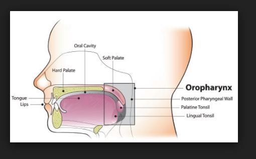
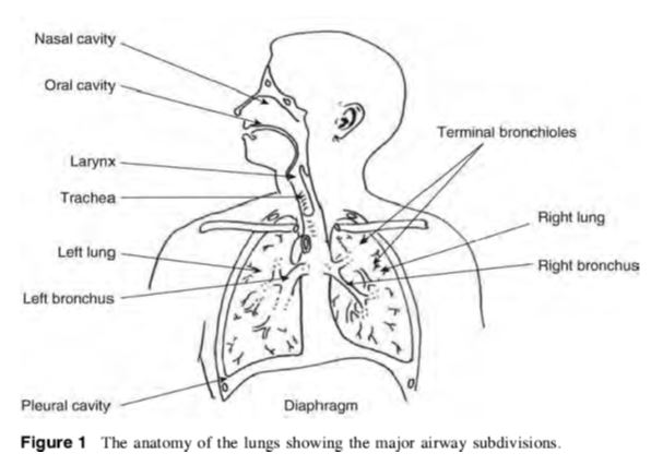
Anatomy and Physiology Of human respiratory system is a complicated organ system of very close structure– function relationships. The system consisted of two regions: the conducting airway and the respiratory region. The airway is further divided into many folds: nasal cavity and the associated sinuses, and the nasopharynx, oropharynx, larynx, trachea, bronchi, and bronchioles. The respiratory region consists of respiratory bronchioles, alveolar ducts, and alveolar sacs.

ANATOMY AND PHYSIOLOGY OF HUMAN RESPIRATORY TRACT:

               The respiratory system works with the circulatory system to deliver oxygen from the lungs to the cells and remove carbon dioxide, and return it to the lungs to be exhaled. The exchange of oxygen and carbon dioxide between the air, blood and body tissues is known as respiration. Healthy lungs take in about 1 pint of air about 12–15 times each minute. All of the blood in the body is passed through the lungs every minute. The respiratory tract is divided into two main parts: the upper respiratory tract, consisting of the nose, nasal cavity and the pharynx; and the lower respiratory tract consisting of the larynx, trachea, bronchi and the lungs The trachea, which begins at the edge of the larynx, divides into two bronchi and continues into the lungs. The trachea allows air to pass from the larynx to the bronchi and then to the lungs. The bronchi divide into smaller bronchioles which branch in the lungs forming passageways for air. The terminal parts of the bronchi are the alveoli. The alveoli are the functional units of the lungs and they form the site of gaseous exchange     

ANATOMY & PHYSIOLOGY Of Human Respiratory Tract

            The blood barrier between the alveolar space and the pulmonary capillaries is very thin to allow for rapid gas exchange. During inspiration, oxygen diffuses through the alveoli walls and the interstitial space, into the blood. Carbon dioxide diffuses in the opposite direction during exhalation. Alveoli are small and there are approximately 300 million of them in each lung. Although alveoli are tiny structures, they have a very large surface area in total (~100 m2) for performing efficient gas exchange.

                     The alveoli form a honeycomb of cells around the spiral, cylindrical surface of the alveolar duct. The exposed alveolar surface is normally covered with a surface film of lipoprotein material.

                      There are several types of pulmonary alveolar cells. Type I (or small type A), are non-phagocytic, membranous pneumocytes. These surface-lining epithelial cells are approximately 5 μm in thickness and possess thin squamous cytoplasmic extensions that originate from a central nucleated portion. These portions do not have any organelles and hence they are metabolically dependent on the central portion of the cell. This reduces their ability to repair themselves if damaged. Attached to the basement membrane are the larger alveolar cells (Type II, type B or septal cells). These rounded, granular, epithelial pneumocytes are approximately 10 to 15 μm tick. There are 6 to 7 cells per alveolus and these cells possess great metabolic activity. They are believed to produce the surfactant material that lines the lung and to be essential for alveolar repair after damage from viruses or chemical agents.

             Amongst, the important roles of the lungs, one can cite: (i) supply oxygen, (ii) remove wastes and toxins, and (iii) defend against hostile intruders. The lungs have three dozen distinct types of cells. Some of these cells scavenge foreign matter. Others have cilia that sweep the mucous membranes lining the smallest air passages. Some cells act on blood pressure control, while others spot infection invaders.

 anatomy of lungs            

      The respiratory system is susceptible to a number of diseases, and the lungs are prone to a wide range of disorders caused by genetic factors, infection and pollutants in the air. The most common problems of the respiratory system are:

  • Asthma
  • Bronchiolitis
  • Chronic obstructive pulmonary disease (COPD)
  • Common cold
  • Cough
  • Cystic fibrosis (CF)
  • Lung cancer
  • Pneumonia
  • Pulmonary hypertension

PRINCIPAL MECHANISMS OF RESPIRATORY DEPOSITION

            The deposition of inhaled particles in the different regions of the respiratory system is very complex, and depends on many factors. Some of the factors influencing respiratory deposition include:

  • Breathing rate
  • Mouth or nose breathing
  • Lung volume
  • Respiration volume
  • Health of the individual
  • Bifurcations in the airways result in a constantly changing hydrodynamic flow field.

Depending on the particle size, airflow, and location in the respiratory system, particle deposition occurs via on of the following principal mechanisms:

Impaction

         Each time the airflow changes due to a bifurcation in the airways, the suspended particles tend to travel along their original path due to inertia and may impact on an airway surface. This mechanism is highly dependent on aerodynamic diameter, since the stopping distance for very small particles is quite low. Impaction occurs mostly in the case of larger particles that are very close to airway walls, near the first airway bifurcations. Therefore, deposition by impaction is greatest in the bronchial region. Impaction accounts for the majority of particle deposition on a mass basis.

 Sedimentation

           Sedimentation is the settling out of particles in the smaller airways of the bronchioles and alveoli, where the air flow is low and airway dimensions are small. The rate of sedimentation is dependent on the terminal settling velocity of the particles, so sedimentation plays a greater role in the deposition of particles with larger aerodynamic diameters. Hygroscopic particles may grow in size as they pass through the warm, humid air passages, thus increasing the probability of deposition by sedimentation.

 Interception

            Interception occurs when a particle contacts an airway surface due to its physical size or shape. Unlike impaction, particles that are deposited by interception do not deviate from their air streamlines. Interception is most likely to occur in small airways or when the air streamline is close to an airway wall. Interception is most significant for fibers, which easily contact airway surfaces do to their length. Furthermore, fibers have small aerodynamic diameters relative to their size, so they can often reach the smallest airways.


Diffusion

Diffusion is the primary mechanism of deposition for particles less than 0.5 microns in diameter and is governed by geometric rather than aerodynamic size. Diffusion is the net transport of particles from a region of high concentration to a region of lower concentration due to Brownian motion. Brownian motion is the random wiggling motion of a particle due to the constant bombardment of air molecules. Diffusional deposition occurs mostly when the particles have just entered the nasopharynx, and is also most likely to occur in the smaller airways of the pulmonary (alveolar) region, where air flow is low.


 Absorption – bioavailability of drugs

Although inhaled drugs have been used for over 50 years to treat airway disease and are in development or being considered for the treatment of many other lung diseases, insulin is at present time the only one representative inhaled drug on the market for systemic disease. Exubera® (insulin human [rDNA origin] inhalation powder is the first diabetes treatment which can be inhaled. Exubera® helps control high blood sugar, works in adults with type 1 diabetes and with type 2 diabetes as well This therapeutic success has lead a number of other companies to investigate and to advance clinical trials as inhaled formulations for systemic applications with a variety of large molecules (leuprolide, a luteinizing hormone-releasing hormone (LHRH) analogue, …). Recent advances in the development of particle technologies and devices now make it possible to formulate, stabilize, and accurately deliver almost any drug to the lungs.

             The pulmonary membrane is naturally permeable to small molecule drugs and to many therapeutic peptides and proteins. The epithelium of the lung, the significant barrier to absorption of inhaled drugs, is thick (50–60 μm) in the trachea, but diminishes in thickness to an extremely thin 0.2 μm in the alveoli. The change in cell types and morphology going from trachea, bronchi, and bronchioles to alveoli is very dramatic. The lungs are for more permeable to macromolecules than any other portal of entry into the body. Some of the most promising therapeutic agents are peptides and proteins, which could be inhaled instead of injected, thereby improving compliance .Particularly, peptides that have been chemically altered to inhibit peptidase enzymes exhibit very high bioavailabilities by the pulmonary route .Indeed, natural mammalian peptides, les than 30 amino acids (somatostatin, vaso active intestinal peptide [VIP], and glucagons), are broken down in the lung by ubiquitous peptidases and have very poor bioavailabilities. Conversely, proteins with molecular weights between 6000 and 50,000 Da are relatively resistant to most peptidases and have good bioavailabilities following inhalation. For larger proteins, the bioavailabilities and absorption mechanisms are not well completely elucidated.

ADVANTAGES OF PULMONARY DRUG DELIVERY SYSTEM


  1. The ability to nebulize viscous drug formulations for pulmonary delivery, thereby overcoming drug solubility issues with the ability to use lipid, water or lipid/water emulsions as drug carriers.
  2. Ability to nebulize viscous liquids into droplets in the 2-5μm range regardless of the carrier composition solubility which would allow for a wide range of drug formulation options.
  3. Increased drug delivery efficacy due to size-stable aerosol droplets with reduced

hygroscopic growth and evaporative shrinkage.

  1. Liposomal drug formulations remain stable when nebulized.
  2. Ability to nebulize protein-containing solutions.
  3. For hand held inhaler applications, drug does not need to be emulsified in liquefied nebulizing gas to achieve aerosolization.

[PPT PDF] Pharmaceutical Water System Validation – IDENTIFICATION OF MICROORGANISMS

[PPT PDF] Pharmaceutical Water System Validation - IDENTIFICATION OF MICROORGANISMS

IDENTIFICATION OF MICROORGANISMS – Pharmaceutical Water System Validation

Identifying the isolates recovered from water monitoring methods may be important in instances where specific waterborne microorganisms may be detrimental to the products or processes in which the water is used. Microorganism information such as this may also be useful when identifying the source of microbial contamination in a product or process. Often a limited group of microorganisms is routinely recovered from a water system. After repeated recovery and characterization, an experienced microbiologist may become proficient at their identification based on only a few recognizable traits such as colonial morphology and staining characteristics. This may allow for a reduction in the number of identifications to representative colony types, or, with proper analyst qualification, may even allow testing short cuts to be taken for these microbial identifications.

ALERT AND ACTION LEVELS AND SPECIFICATIONS

Though the use of alert and action levels is most often associated with microbial data, they can be associated with any attribute. In pharmaceutical water systems, almost every quality attribute, other than microbial quality, can be very rapidly determined with near-real time results. These short-delay data can give immediate system performance feedback, serving as ongoing process control indicators. However, because some attributes may not continuously be monitored or have a long delay in data availability (like microbial monitoring data), properly established Alert and Action Levels can serve as an early warning or indication of a potentially approaching quality shift occurring between or at the next periodic monitoring. In a validated water system, process controls should yield relatively constant and more than adequate values for these monitored attributes such that their Alert and Action Levels are infrequently broached.

As process control indicators, alert and action levels are designed to allow remedial action to occur that will prevent a system from deviating completely out of control and producing water unfit for its intended use. This “intended use” minimum quality is sometimes referred to as a “specification” or “limit”. In the opening paragraphs of this chapter, rationale was presented for no microbial specifications being included within the body of the bulk water (Purified Water and Water for Injection) monographs. This does not mean that the user should not have microbial specifications for these waters. To the contrary, in most situations such specifications should be established by the user. The microbial specification should reflect the maximum microbial level at which the water is still fit for use without compromising the quality needs of the process or product where the water is used. Because water from a given system may have many uses, the most stringent of these uses should be used to establish this specification.

Where appropriate, a microbial specification could be qualitative as well as quantitative. In other words, the number of total microorganisms may be as important as the number of a specific microorganism or even the absence of a specific microorganism. Microorganisms that are known to be problematic could include opportunistic or overt pathogens, nonpathogenic indicators of potentially undetected pathogens, or microorganisms known to compromise a process or product, such as by being resistant to a preservative or able to proliferate in or degrade a product. These microorganisms comprise an often ill-defined group referred to as “objectionable microorganisms”. Because objectionable is a term relative to the water’s use, the list of microorganisms in such a group should be tailored to those species with the potential to be present and problematic. Their negative impact is most often demonstrated when they are present in high numbers, but depending on the species, an allowable level may exist, below which they may not be considered objectionable.

[PPT PDF] Pharmaceutical Water System Validation – IDENTIFICATION OF MICROORGANISMS IDENTIFICATION OF MICROORGANISMS – Pharmaceutical warer system ppt [PPT PDF] Pharmaceutical Water System Validation - IDENTIFICATION OF MICROORGANISMS

As stated above, alert and action levels for a given process control attribute are used to help maintain system control and avoid exceeding the pass/fail specification for that attribute. Alert and action levels may be both quantitative and qualitative. They may involve levels of total microbial counts or recoveries of specific microorganisms. Alert levels are events or levels that, when they occur or are exceeded, indicate that a process may have drifted from its normal operating condition. Alert level excursions constitute a warning and do not necessarily require a corrective action. However, alert level excursions usually lead to the alerting of personnel involved in water system operation as well as QA. Alert level excursions may also lead to additional monitoring with more intense scrutiny of resulting and neighboring data as well as other process indicators. Action levels are events or higher levels that, when they occur or are exceeded, indicate that a process is probably drifting from its normal operating range. Examples of kinds of action level “events” include exceeding alert levels repeatedly; or in multiple simultaneous locations, a single occurrence of exceeding a higher microbial level; or the individual or repeated recovery of specific objectionable microorganisms. Exceeding an action level should lead to immediate notification of both QA and personnel involved in water system operations so that corrective actions can immediately be taken to bring the process back into its normal operating range. Such remedial actions should also include efforts to understand and eliminate or at least reduce the incidence of a future occurrence. A root cause investigation may be necessary to devise an effective preventative action strategy. Depending on the nature of the action level excursion, it may also be necessary to evaluate its impact on the water uses during that time. Impact evaluations may include delineation of affected batches and additional or more extensive product testing. It may also involve experimental product challenges.

Alert and action levels should be derived from an evaluation of historic monitoring data called a trend analysis. Other guidelines on approaches that may be used, ranging from “inspectional”to statistical evaluation of the historical data have been published. The ultimate goal is to understand the normal variability of the data during what is considered a typical operational period. Then, trigger points or levels can be established that will signal when future data may be approaching (alert level) or exceeding (action level) the boundaries of that “normal variability”. Such alert and action levels are based on the control capability of the system as it was being maintained and controlled during that historic period of typical control.

In new water systems where there is very limited or no historic data from which to derive data trends, it is common to simply establish initial alert and action levels based on a combination of equipment design capabilities but below the process and product specifications where water is used. It is also common, especially for ambient water systems, to microbiologically “mature” over the first year of use. By the end of this period, a relatively steady state microbial population (microorganism types and levels) will have been allowed or promoted to develop as a result of the collective effects of routine system maintenance and operation, including the frequency of unit operation rebeddings, backwashings, regenerations, and sanitizations. This microbial population will typically be higher than was seen when the water system was new, so it should be expected that the data trends (and the resulting alert and action levels) will increase over this “maturation” period and eventually level off.

Pharmaceutical water System

A water system should be designed so that performance-based alert and action levels are well below water specifications. With poorly designed or maintained water systems, the system owner may find that initial new system microbial levels were acceptable for the water uses and specifications, but the mature levels are not. This is a serious situation, which if not correctable with more frequent system maintenance and sanitization, may require expensive water system renovation or even replacement. Therefore, it cannot be overemphasized that water systems should be designed for ease of microbial control, so that when monitored against alert and action levels, and maintained accordingly, the water continuously meets all applicable specifications.

An action level should not be established at a level equivalent to the specification. This leaves no room for remedial system maintenance that could avoid a specification excursion. Exceeding a specification is a far more serious event than an action level excursion. A specification excursion may trigger an extensive finished product impact investigation, substantial remedial actions within the water system that may include a complete shutdown, and possibly even product rejection.

Another scenario to be avoided is the establishment of an arbitrarily high and usually nonperformance based action level. Such unrealistic action levels deprive users of meaningful indicator values that could trigger remedial system maintenance. Unrealistically high action levels allow systems to grow well out of control before action is taken, when their intent should be to catch a system imbalance before it goes wildly out of control.

Because alert and action levels should be based on actual system performance, and the system performance data are generated by a given test method, it follows that those alert and action levels should be valid only for test results generated by the same test method. It is invalid to apply alert and action level criteria to test results generated by a different test method. The two test methods may not equivalently recover microorganisms from the same water samples. Similarly invalid is the use of trend data to derive alert and action levels for one water system, but applying those alert and action levels to a different water system. Alert and action levels are water system and test method specific.

Nevertheless, there are certain maximum microbial levels above which action levels should never be established. Water systems with these levels should unarguably be considered out of control. Using the microbial enumeration methodologies suggested above, generally considered maximum action levels are 100 cfu per mL for Purified Water and 10 cfu per 100 mL for Water for Injection. However, if a given water system controls microorganisms much more tightly than these levels, appropriate alert and action levels should be established from these tighter control levels so that they can truly indicate when water systems may be starting to trend out of control. These in-process microbial control parameters should be established well below the user-defined microbial specifications that delineate the water’s fitness for use.

Special consideration is needed for establishing maximum microbial action levels for Drinking Water because the water is often delivered to the facility in a condition over which the user has little control. High microbial levels in Drinking Water may be indicative of a municipal water system upset, broken water main, or inadequate disinfection, and therefore, potential contamination with objectionable microorganisms. Using the suggested microbial enumeration methodology, a reasonable maximum action level for Drinking Water is 500 cfu per mL. Considering the potential concern for objectionable microorganisms raised by such high microbial levels in the feedwater, informing the municipality of the problem so they may begin corrective actions should be an immediate first step. In-house remedial actions may or may not also be needed, but could include performing additional coliform testing on the incoming water and pretreating the water with either additional chlorination or UV light irradiation or filtration or a combination of approaches.

Source : USP

Expert Committee : (PW05) Pharmaceutical Waters 05

USP29–NF24 Page 3056

Pharmacopeial Forum : Volume No. 30(5) Page 1744

Pharmaceutical Water System Ppt,

Pharmaceutical Water Systems,

Purified Water Specification As Per Usp,

Pharmaceutical Water System Design Operation And Validation Pdf,

pharmaceutical water system design operation and validation,

pharmaceutical water system ppt – What is Pharmaceutical water,

purified water & Water for Injection SOP as per usp,

Pharmaceutical Water Systems: Storage & Distribution Systems,

pharmaceutical water system : Inspection of Pharmaceutical water systems,

pharmaceutical water Production : Water purification systems,

Pharmaceutical Water Systems: Types: Water quality specifications,

Pharmaceutical Water System: principles for pharmaceutical water systems

[PPT PDF] Pharmaceutical Water System Design Validation -UNIT OPERATIONS CONCERNS

[PPT PDF] Pharmaceutical Water System Design Validation -UNIT OPERATIONS CONCERNS im

UNIT OPERATIONS CONCERNS

The following is a brief description of selected unit operations and the operation and validation concerns associated with them. Not all unit operations are discussed, nor are all potential problems addressed. The purpose is to highlight issues that focus on the design, installation, operation, maintenance, and monitoring parameters that facilitate water system validation.

Prefiltration

The purpose of prefiltration—also referred to as initial, coarse, or depth filtration—is to remove solid contaminants down to a size of 7 to 10 µm from the incoming source water supply and protect downstream system components from particulates that can inhibit equipment performance and shorten their effective life. This coarse filtration technology utilizes primarily sieving effects for particle capture and a depth of filtration medium that has a high “dirt load” capacity. Such filtration units are available in a wide range of designs and for various applications. Removal efficiencies and capacities differ significantly, from granular bed filters such as multimedia or sand for larger water systems, to depth cartridges for smaller water systems. Unit and system configurations vary widely in type of filtering media and location in the process. Granular or cartridge prefilters are often situated at or near the head of the water pretreatment system prior to unit operations designed to remove the source water disinfectants. This location, however, does not preclude the need for periodic microbial control because biofilm can still proliferate, although at a slower rate in the presence of source water disinfectants. Design and operational issues that may impact performance of depth filters include channeling of the filtering media, blockage from silt, microbial growth, and filtering-media loss during improper backwashing. Control measures involve pressure and flow monitoring during use and backwashing, sanitizing, and replacing filtering media. An important design concern is sizing of the filter to prevent channeling or media loss resulting from inappropriate water flow rates as well as proper sizing to minimize excessively frequent or infrequent backwashing or cartridge filter replacement.

Activated Carbon

Granular activated carbon beds adsorb low molecular weight organic material and oxidizing additives, such as chlorine and chloramine compounds, removing them from the water. They are used to achieve certain quality attributes and to protect against reaction with downstream stainless steel surfaces, resins, and membranes. The chief operating concerns regarding activated carbon beds include the propensity to support bacteria growth, the potential for hydraulic channeling, the organic adsorption capacity, appropriate water flow rates and contact time, the inability to be regenerated in situ, and the shedding of bacteria, endotoxins, organic chemicals, and fine carbon particles. Control measures may involve monitoring water flow rates and differential pressures, sanitizing with hot water or steam, backwashing, testing for adsorption capacity, and frequent replacement of the carbon bed. If the activated carbon bed is intended for organic reduction, it may also be appropriate to monitor influent and effluent TOC. It is important to note that the use of steam for carbon bed sanitization is often incompletely effective due to steam channeling rather than even permeation through the bed. This phenomenon can usually be avoided by using hot water sanitization. It is also important to note that microbial biofilm development on the surface of the granular carbon particles (as well as on other particles such as found in deionizer beds and even multimedia beds) can cause adjacent bed granules to “stick” together. When large masses of granules are agglomerated in this fashion, normal backwashing and bed fluidization flow parameters may not be sufficient to disperse them, leading to ineffective removal of trapped debris, loose biofilm, and penetration of microbial controlling conditions (as well as regenerant chemicals as in the case of agglomerated deionizer resins). Alternative technologies to activated carbon beds can be used in order to avoid their microbial problems, such as disinfectant-neutralizing chemical additives and regenerable organic scavenging devices. However, these alternatives do not function by the same mechanisms as activated carbon, may not be as effective at removing disinfectants and some organics, and have a different set of operating concerns and control measures that may be nearly as troublesome as activated carbon beds.

Additives

Chemical additives are used in water systems (a) to control microorganisms by use of sanitants such as chlorine compounds and ozone, (b) to enhance the removal of suspended solids by use of flocculating agents, (c) to remove chlorine compounds, (d) to avoid scaling on reverse osmosis membranes, and (e) to adjust pH for more effective removal of carbonate and ammonia compounds by reverse osmosis. These additives do not constitute “added substances” as long as they are either removed by subsequent processing steps or are otherwise absent from the finished water. Control of additives to ensure a continuously effective concentration and subsequent monitoring to ensure their removal should be designed into the system and included in the monitoring program.

Organic Scavengers

Organic scavenging devices use macroreticular weakly basic anion-exchange resins capable of removing organic material and endotoxins from the water. They can be regenerated with appropriate biocidal caustic brine solutions. Operating concerns are associated with organic scavenging capacity, particulate, chemical and microbiological fouling of the reactive resin surface, flow rate, regeneration frequency, and shedding of resin fragments. Control measures include TOC testing of influent and effluent, backwashing, monitoring hydraulic performance, and using downstream filters to remove resin fines.

Softeners

Water softeners may be located either upstream or downstream of disinfectant removal units. They utilize sodium-based cation-exchange resins to remove water-hardness ions, such as calcium and magnesium, that could foul or interfere with the performance of downstream processing equipment such as reverse osmosis membranes, deionization devices, and distillation units. Water softeners can also be used to remove other lower affinity cations, such as the ammonium ion, that may be released from chloramine disinfectants commonly used in drinking water and which might otherwise carryover through other downstream unit operations. If ammonium removal is one of its purposes, the softener must be located downstream of the disinfectant removal operation, which itself may liberate ammonium from neutralized chloramine disinfectants. Water softener resin beds are regenerated with concentrated sodium chloride solution (brine). Concerns include microorganism proliferation, channeling caused by biofilm agglomeration of resin particles, appropriate water flow rates and contact time, ion-exchange capacity, organic and particulate resin fouling, organic leaching from new resins, fracture of the resin beads, resin degradation by excessively chlorinated water, and contamination from the brine solution used for regeneration. Control measures involve recirculation of water during periods of low water use, periodic sanitization of the resin and brine system, use of microbial control devices (e.g., UV light and chlorine), locating the unit upstream of the disinfectant removal step (if used only for softening), appropriate regeneration frequency, effluent chemical monitoring (e.g., hardness ions and possibly ammonium), and downstream filtration to remove resin fines. If a softener is used for ammonium removal from chloramine-containing source water, then capacity, contact time, resin surface fouling, pH, and regeneration frequency are very important.

Deionization

Deionization (DI), and continuous electrodeionization (CEDI) are effective methods of improving the chemical quality attributes of water by removing cations and anions. DI systems have charged resins that require periodic regeneration with an acid and base. Typically, cationic resins are regenerated with either hydrochloric or sulfuric acid, which replace the captured positive ions with hydrogen ions. Anionic resins are regenerated with sodium or potassium hydroxide, which replace captured negative ions with hydroxide ions. Because free endotoxin is negatively charged, there is some removal of endotoxin achieved by the anionic resin. Both regenerant chemicals are biocidal and offer a measure of microbial control. The system can be designed so that the cation and anion resins are in separate or “twin” beds or they can be mixed together to form a mixed bed. Twin beds are easily regenerated but deionize water less efficiently than mixed beds, which have a considerably more complex regeneration process. Rechargeable resin canisters can also be used for this purpose.

[PPT PDF] Pharmaceutical Water System Design Validation -UNIT OPERATIONS CONCERNS

[PPT PDF] Pharmaceutical Water System Design Validation -UNIT OPERATIONS CONCERNS[PPT PDF] Pharmaceutical Water System Design Validation -UNIT OPERATIONS CONCERNS im[PPT PDF] Pharmaceutical Water System Design Validation -UNIT OPERATIONS CONCERNS


The CEDI system uses a combination of mixed resin, selectively permeable membranes, and an electric charge, providing continuous flow (product and waste concentrate) and continuous regeneration. Water enters both the resin section and the waste (concentrate) section. As it passes through the resin, it is deionized to become product water. The resin acts as a conductor enabling the electrical potential to drive the captured cations and anions through the resin and appropriate membranes for concentration and removal in the waste water stream. The electrical potential also separates the water in the resin (product) section into hydrogen and hydroxide ions. This permits continuous regeneration of the resin without the need for regenerant additives. However, unlike conventional deionization, CEDI units must start with water that is already partially purified because they generally cannot produce Purified Waterquality when starting with the heavier ion load of unpurified source water.

Concerns for all forms of deionization units include microbial and endotoxin control, chemical additive impact on resins and membranes, and loss, degradation, and fouling of resin. Issues of concern specific to DI units include regeneration frequency and completeness, channeling, caused by biofilm agglomeration of resin particles, organic leaching from new resins, complete resin separation for mixed bed regeneration, and mixing air contamination (mixed beds). Control measures vary but typically include recirculation loops, effluent microbial control by UV light, conductivity monitoring, resin testing, microporous filtration of mixing air, microbial monitoring, frequent regeneration to minimize and control microorganism growth, sizing the equipment for suitable water flow and contact time, and use of elevated temperatures. Internal distributor and regeneration piping for mixed bed units should be configured to ensure that regeneration chemicals contact all internal bed and piping surfaces and resins. Rechargeable canisters can be the source of contamination and should be carefully monitored. Full knowledge of previous resin use, minimum storage time between regeneration and use, and appropriate sanitizing procedures are critical factors ensuring proper performance.

Reverse Osmosis

Reverse osmosis (RO) units employ semipermeable membranes. The “pores” of RO membranes are actually intersegmental spaces among the polymer molecules. They are big enough for permeation of water molecules, but too small to permit passage of hydrated chemical ions. However, many factors including pH, temperature, and differential pressure across the membrane affect the selectivity of this permeation. With the proper controls, RO membranes can achieve chemical, microbial, and endotoxin quality improvement. The process streams consist of supply water, product water (permeate), and wastewater (reject). Depending on source water, pretreatment and system configuration variations and chemical additives may be necessary to achieve desired performance and reliability.

A major factor affecting RO performance is the permeate recovery rate, that is, the amount of the water passing through the membrane compared to the amount rejected. This is influenced by the several factors, but most significantly by the pump pressure. Recoveries of 75% are typical, and can accomplish a 1 to 2 log purification of most impurities. For most feed waters, this is usually not enough to meet Purified Water conductivity specifications. A second pass of this permeate water through another RO stage usually achieves the necessary permeate purity if other factors such as pH and temperature have been appropriately adjusted and the ammonia from chloraminated source water has been previously removed. Increasing recoveries with higher pressures in order to reduce the volume of reject water will lead to reduced permeate purity. If increased pressures are needed over time to achieve the same permeate flow, this is an indication of partial membrane blockage that needs to be corrected before it becomes irreversibly fouled, and expensive membrane replacement is the only option.

Other concerns associated with the design and operation of RO units include membrane materials that are extremely sensitive to sanitizing agents and to particulate, chemical, and microbial membrane fouling; membrane and seal integrity; the passage of dissolved gases, such as carbon dioxide and ammonia; and the volume of wastewater, particularly where water discharge is tightly regulated by local authorities. Failure of membrane or seal integrity will result in product water contamination. Methods of control involve suitable pretreatment of the influent water stream, appropriate membrane material selection, integrity challenges, membrane design and heat tolerance, periodic sanitization, and monitoring of differential pressures, conductivity, microbial levels, and TOC.

The development of RO units that can tolerate sanitizing water temperatures as well as operate efficiently and continuously at elevated temperatures has added greatly to their microbial control and to the avoidance of biofouling. RO units can be used alone or in combination with DI and CEDI units as well as ultrafiltration for operational and quality enhancements.

Ultrafiltration

Ultrafiltration is a technology most often employed in pharmaceutical water systems for removing endotoxins from a water stream. It can also use semipermeable membranes, but unlike RO, these typically use polysulfone membranes whose intersegmental “pores” have been purposefully exaggerated during their manufacture by preventing the polymer molecules from reaching their smaller equilibrium proximities to each other. Depending on the level of equilibrium control during their fabrication, membranes with differing molecular weight “cutoffs” can be created such that molecules with molecular weights above these cutoffs ratings are rejected and cannot penetrate the filtration matrix.

Ceramic ultrafilters are another molecular sieving technology. Ceramic ultrafilters are self supporting and extremely durable, backwashable, chemically cleanable, and steam sterilizable. However, they may require higher operating pressures than membrane type ultrafilters.

All ultrafiltration devices work primarily by a molecular sieving principle. Ultrafilters with molecular weight cutoff ratings in the range of 10,000 to 20,000 Da are typically used in water systems for removing endotoxins. This technology may be appropriate as an intermediate or final purification step. Similar to RO, successful performance is dependent upon pretreatment of the water by upstream unit operations.

Issues of concern for ultrafilters include compatibility of membrane material with heat and sanitizing agents, membrane integrity, fouling by particles and microorganisms, and seal integrity. Control measures involve filtration medium selection, sanitization, flow design (dead end vs. tangential), integrity challenges, regular cartridge changes, elevated feed water temperature, and monitoring TOC and differential pressure. Additional flexibility in operation is possible based on the way ultrafiltration units are arranged such as in a parallel or series configurations. Care should be taken to avoid stagnant water conditions that could promote microorganism growth in back-up or standby units.

Charge-Modified Filtration

Charge-modified filters are usually microbially retentive filters that are treated during their manufacture to have a positive charge on their surfaces. Microbial retentive filtration will be described in a subsequent section, but the significant feature of these membranes is their electrostatic surface charge. Such charged filters can reduce endotoxin levels in the fluids passing through them by their adsorption (owing to endotoxin’s negative charge) onto the membrane surfaces. Though ultrafilters are more often employed as a unit operation for endotoxin removal in water systems, charge-modified filters may also have a place in endotoxin removal particularly where available upstream pressures are not sufficient for ultrafiltration and for a single, relatively short term use. Charge-modified filters may be difficult to validate for long-term or large-volume endotoxin retention. Even though their purified standard endotoxin retention can be well characterized, their retention capacity for “natural” endotoxins is difficult to gauge. Nevertheless, utility could be demonstrated and validated as short-term, single-use filters at points of use in water systems that are not designed for endotoxin control or where only an endotoxin “polishing” (removal of only slight or occasional endotoxin levels) is needed. Control and validation concerns include volume and duration of use, flow rate, water conductivity and purity, and constancy and concentration of endotoxin levels being removed. All of these factors may have to be evaluated and challenged prior to using this approach, making this a difficult-to-validate application. Even so, there may still be a possible need for additional backup endotoxin testing both upstream and downstream of the filter.

Microbial-Retentive Filtration

Microbial-retentive membrane filters have experienced an evolution of understanding in the past decade that has caused previously held theoretical retention mechanisms to be reconsidered. These filters have a larger effective “pore size” than ultrafilters and are intended to prevent the passage of microorganisms and similarly sized particles without unduly restricting flow. This type of filtration is widely employed within water systems for filtering the bacteria out of both water and compressed gases as well as for vent filters on tanks and stills and other unit operations. However, the properties of the water system microorganisms seem to challenge a filter’s microbial retention from water with phenomena absent from other aseptic filtration applications, such as filter sterilizing of pharmaceutical formulations prior to packaging. In the latter application, sterilizing grade filters are generally considered to have an assigned rating of 0.2 or 0.22 µm. This rather arbitrary rating is associated with filters that have the ability to retain a high level challenge of a specially prepared inoculum of Brevundimonas (formerly Pseudomonas) diminuta.This is a small microorganism originally isolated decades ago from a product that had been “filter sterilized” using a 0.45-µm rated filter. Further study revealed that a percentage of cells of this microorganism could reproducibly penetrate the 0.45-µm sterilizing filters. Through historic correlation of B. diminuta retaining tighter filters, thought to be twice as good as 0.45-µm filter, assigned ratings of 0.2 or 0.22 µm with their successful use in product solution filter sterilization, both this filter rating and the associated high level B. diminuta challenge have become the current benchmarks for sterilizing filtration. New evidence now suggests that for microbial-retentive filters used for pharmaceutical water, B. diminuta may not be the best model microorganism.

An archaic understanding of microbial retentive filtration would lead one to equate a filter’s rating with the false impression of a simple sieve or screen that absolutely retains particles sized at or above the filter’s rating. A current understanding of the mechanisms involved in microbial retention and the variables that can affect those mechanisms has yielded a far more complex interaction of phenomena than previously understood. A combination of simple sieve retention and surface adsorption are now known to contribute to microbial retention.

The following all interact to create some unusual and surprising retention phenomena for water system microorganisms: the variability in the range and average pore sizes created by the various membrane fabrication processes, the variability of the surface chemistry and three-dimensional structure related to the different polymers used in these filter matrices, and the size and surface properties of the microorganism intended to be retained by the filters. B. diminuta may not the best challenge microorganisms for demonstrating bacterial retention for 0.2- to 0.22-µm rated filters for use in water systems because it appears to be more easily retained by these filters than some water system flora. The well-documented appearance of water system microorganisms on the downstream sides of some 0.2- to 0.22-µm rated filters after a relatively short period of use seems to support that some penetration phenomena are at work. Unknown for certain is if this downstream appearance is caused by a “blow-through” or some other pass-through phenomenon as a result of tiny cells or less cell “stickiness”, or by a “growth through” phenomenon as a result of cells hypothetically replicating their way through the pores to the downstream side. Whatever is the penetration mechanism, 0.2- to 0.22-µm rated membranes may not be the best choice for some water system uses.

Microbial retention success in water systems has been reported with the use of some manufacturers’ filters arbitrarily rated as 0.1 µm. There is general agreement that for a given manufacturer, their 0.1-µm rated filters are tighter than their 0.2- to 0.22-µm rated filters. However, comparably rated filters from different manufacturers in water filtration applications may not perform equivalently owing to the different filter fabrication processes and the nonstandardized microbial retention challenge processes currently used for defining the 0.1-µm filter rating. It should be noted that use of 0.1-µm rated membranes generally results in a sacrifice in flow rate compared to 0.2- to 0.22-µm membranes, so whatever membranes are chosen for a water system appliAcation, the user must verify that the membranes are suitable for their intended application, use period, and use process, including flow rate.

For microbial retentive gas filtrations, the same sieving and adsorptive retention phenomena are at work as in liquid filtration, but the adsorptive phenomenon is enhanced by additional electrostatic interactions between particles and filter matrix. These electrostatic interactions are so strong that particle retention for a given filter rating is significantly more efficient in gas filtration than in water or product solution filtrations. These additional adsorptive interactions render filters rated at 0.2 to 0.22 µm unquestionably suitable for microbial retentive gas filtrations. When microbially retentive filters are used in these applications, the membrane surface is typically hydrophobic (non-wettable by water). A significant area of concern for gas filtration is blockage of tank vents by condensed water vapor, which can cause mechanical damage to the tank. Control measures include electrical or steam tracing and a self-draining orientation of vent filter housings to prevent accumulation of vapor condensate. However, a continuously high filter temperature will take an oxidative toll on polypropylene components of the filter, so sterilization of the unit prior to initial use, and periodically thereafter, as well as regular visual inspections, integrity tests, and changes are recommended control methods.

In water applications, microbial retentive filters may be used downstream of unit operations that tend to release microorganisms or upstream of unit operations that are sensitive to microorganisms. Microbial retentive filters may also be used to filter water feeding the distribution system. It should be noted that regulatory authorities allow the use of microbial retentive filters within distribution systems or even at use points if they have been properly validated and are appropriately maintained. A point-of-use filter should only be intended to “polish” the microbial quality of an otherwise well-maintained system and not to serve as the primary microbial control device. The efficacy of system microbial control measures can only be assessed by sampling the water upstream of the filters. As an added measure of protection, in-line UV lamps, appropriately sized for the flow rate (see Sanitization), may be used just upstream of microbial retentive filters to inactivate microorganisms prior to their capture by the filter. This tandem approach tends to greatly delay potential microbial penetration phenomena and can substantially extend filter service life.

Ultraviolet Light

The use of low-pressure UV lights that emit a 254-nm wavelength for microbial control is discussed under Sanitization, but the application of UV light in chemical purification is also emerging. This 254-nm wavelength is also useful in the destruction of ozone. With intense emissions at wavelengths around 185 nm (as well as at 254 nm), medium pressure UV lights have demonstrated utility in the destruction of the chlorine containing disinfectants used in source water as well as for interim stages of water pretreatment. High intensities of this wavelength alone or in combination with other oxidizing sanitants, such as hydrogen peroxide, have been used to lower TOC levels in recirculating distribution systems. The organics are typically converted to carbon dioxide, which equilibrates to bicarbonate, and incompletely oxidized carboxylic acids, both of which can easily be removed by polishing ion-exchange resins. Areas of concern include adequate UV intensity and residence time, gradual loss of UV emissivity with bulb age, gradual formation of UV-absorbing film at the water contact surface, incomplete photodegradation during unforeseen source water hyperchlorination, release of ammonia from chloramine photodegradation, unapparent UV bulb failure, and conductivity degradation in distribution systems using 185-nm UV lights. Control measures include regular inspection or emissivity alarms to detect bulb failures or film occlusions, regular UV bulb sleeve cleaning and wiping, downstream chlorine detectors, downstream polishing deionizers, and regular (approximately yearly) bulb replacement.

Distillation

Distillation units provide chemical and microbial purification via thermal vaporization, mist elimination, and water vapor condensation. A variety of designs is available including single effect, multiple effect, and vapor compression. The latter two configurations are normally used in larger systems because of their generating capacity and efficiency. Distilled water systems require different feed water controls than required by membrane systems. For distillation, due consideration must be given to prior removal of hardness and silica impurities that may foul or corrode the heat transfer surfaces as well as prior removal of those impurities that could volatize and condense along with the water vapor. In spite of general perceptions, even the best distillation process cannot afford absolute removal of contaminating ions and endotoxin. Most stills are recognized as being able to accomplish at least a 3 to 4 log reduction in these impurity concentrations. Areas of concern include carry-over of volatile organic impurities such as trihalomethanes (see Source and Feed Water Considerations) and gaseous impurities such as ammonia and carbon dioxide, faulty mist elimination, evaporator flooding, inadequate blowdown, stagnant water in condensers and evaporators, pump and compressor seal design, pinhole evaporator and condenser leaks, and conductivity (quality) variations during start-up and operation.

Methods of control may involve preliminary decarbonation steps to remove both dissolved carbon dioxide and other volatile or noncondensable impurities; reliable mist elimination to minimize feedwater droplet entrainment; visual or automated high water level indication to detect boiler flooding and boil over; use of sanitary pumps and compressors to minimize microbial and lubricant contamination of feedwater and condensate; proper drainage during inactive periods to minimize microbial growth and accumulation of associated endotoxin in boiler water; blow down control to limit the impurity concentration effect in the boiler to manageable levels; on-line conductivity sensing with automated diversion to waste to prevent unacceptable water upon still startup or still malfunction from getting into the finished water distribute system; and periodic integrity testing for pinhole leaks to routinely assure condensate is not compromised by nonvolatized source water contaminants.

Storage Tanks

Storage tanks are included in water distribution systems to optimize processing equipment capacity. Storage also allows for routine maintenance within the pretreatment train while maintaining continuous supply to meet manufacturing needs. Design and operation considerations are needed to prevent or minimize the development of biofilm, to minimize corrosion, to aid in the use of chemical sanitization of the tanks, and to safeguard mechanical integrity. These considerations may include using closed tanks with smooth interiors, the ability to spray the tank headspace using sprayballs on recirculating loop returns, and the use of heated, jacketed/insulated tanks. This minimizes corrosion and biofilm development and aids in thermal and chemical sanitization. Storage tanks require venting to compensate for the dynamics of changing water levels. This can be accomplished with a properly oriented and heat-traced filter housing fitted with a hydrophobic microbial retentive membrane filter affixed to an atmospheric vent. Alternatively, an automatic membrane-filtered compressed gas blanketing system may be used. In both cases, rupture disks equipped with a rupture alarm device should be used as a further safeguard for the mechanical integrity of the tank. Areas of concern include microbial growth or corrosion due to irregular or incomplete sanitization and microbial contamination from unalarmed rupture disk failures caused by condensate-occluded vent filters.

Distribution Systems

Distribution system configuration should allow for the continuous flow of water in the piping by means of recirculation. Use of nonrecirculating, dead-end, or one-way systems or system segments should be avoided whenever possible. If not possible, these systems should be periodically flushed and more closely monitored. Experience has shown that continuously recirculated systems are easier to maintain. Pumps should be designed to deliver fully turbulent flow conditions to facilitate thorough heat distribution (for hot water sanitized systems) as well as thorough chemical sanitant distribution. Turbulent flow also appear to either retard the development of biofilms or reduce the tendency of those biofilms to shed bacteria into the water. If redundant pumps are used, they should be configured and used to avoid microbial contamination of the system.

Components and distribution lines should be sloped and fitted with drain points so that the system can be completely drained. In stainless steel distribution systems where the water is circulated at a high temperature, dead legs and low-flow conditions should be avoided, and valved tie-in points should have length-to-diameter ratios of six or less. If constructed of heat tolerant plastic, this ratio should be even less to avoid cool points where biofilm development could occur. In ambient temperature distribution systems, particular care should be exercised to avoid or minimize dead leg ratios of any size and provide for complete drainage. If the system is intended to be steam sanitized, careful sloping and low-point drainage is crucial to condensate removal and sanitization success. If drainage of components or distribution lines is intended as a microbial control strategy, they should also be configured to be completely dried using dry compressed air (or nitrogen if appropriate employee safety measures are used). Drained but still moist surfaces will still support microbial proliferation. Water exiting from the distribution system should not be returned to the system without first passing through all or a portion of the purification train.

The distribution design should include the placement of sampling valves in the storage tank and at other locations, such as in the return line of the recirculating water system. Where feasible, the primary sampling sites for water should be the valves that deliver water to the points of use. Direct connections to processes or auxiliary equipment should be designed to prevent reverse flow into the controlled water system. Hoses and heat exchangers that are attached to points of use in order to deliver water for a particular use must not chemically or microbiologically degrade the water quality. The distribution system should permit sanitization for microorganism control. The system may be continuously operated at sanitizing conditions or sanitized periodically.

Source : USP

Expert Committee : (PW05) Pharmaceutical Waters 05

USP29–NF24 Page 3056

Pharmacopeial Forum : Volume No. 30(5) Page 1744

Pharmaceutical Water System Ppt,

Pharmaceutical Water Systems,

Purified Water Specification As Per Usp,

Pharmaceutical Water System Design Operation And Validation Pdf,

pharmaceutical water system design operation and validation,

pharmaceutical water system ppt – What is Pharmaceutical water,

purified water & Water for Injection SOP as per usp,

Pharmaceutical Water Systems: Storage & Distribution Systems,

pharmaceutical water system : Inspection of Pharmaceutical water systems,

pharmaceutical water Production : Water purification systems,

Pharmaceutical Water Systems: Types: Water quality specifications,

Pharmaceutical Water System: principles for pharmaceutical water systems

[PPT PDF] Pharmaceutical Water System Design Validation -SAMPLING CONSIDERATIONS

[PPT PDF] Pharmaceutical Water System Design Validation -SAMPLING CONSIDERATIONS

Pharmaceutical Water System- SAMPLING CONSIDERATIONS

Water systems should be monitored at a frequency that is sufficient to ensure that the system is in control and continues to produce water of acceptable quality. Samples should be taken from representative locations within the processing and distribution system. Established sampling frequencies should be based on system validation data and should cover critical areas including unit operation sites. The sampling plan should take into consideration the desired attributes of the water being sampled. For example, systems for Water for Injection because of their more critical microbiological requirements, may require a more rigorous sampling frequency.

Analyses of water samples often serve two purposes: in-process control assessments and final quality control assessments. In-process control analyses are usually focused on the attributes of the water within the system. Quality control is primarily concerned with the attributes of the water delivered by the system to its various uses. The latter usually employs some sort of transfer device, often a flexible hose, to bridge the gap between the distribution system use-point valve and the actual location of water use. The issue of sample collection location and sampling procedure is often hotly debated because of the typically mixed use of the data generated from the samples, for both in-process control and quality control. In these single sample and mixed data use situations, the worst-case scenario should be utilized. In other words, samples should be collected from use points using the same delivery devices, such as hoses, and procedures, such as preliminary hose or outlet flushing, as are employed by production from those use points. Where use points per se cannot be sampled, such as hard-piped connections to equipment, special sampling ports may be used. In all cases, the sample must represent as closely as possible the quality of the water used in production. If a point of use filter is employed, sampling of the water prior to and after the filter is needed because the filter will mask the microbial control achieved by the normal operating procedures of the system.

Samples containing chemical sanitizing agents require neutralization prior to microbiological analysis. Samples for microbiological analysis should be tested immediately, or suitably refrigerated to preserve the original microbial attributes until analysis can begin. Samples of flowing water are only indicative of the concentration of planktonic (free floating) microorganisms present in the system. Biofilm microorganisms (those attached to water system surfaces) are usually present in greater numbers and are the source of the planktonic population recovered from grab samples. Microorganisms in biofilms represent a continuous source of contamination and are difficult to directly sample and quantify. Consequently, the planktonic population is usually used as an indicator of system contamination levels and is the basis for system Alert and Action Levels. The consistent appearance of elevated planktonic levels is usually an indication of advanced biofilm development in need of remedial control. System control and sanitization are key in controlling biofilm formation and the consequent planktonic population.

Sampling for chemical analyses is also done for in-process control and for quality control purposes. However, unlike microbial analyses, chemical analyses can be and often are performed using on-line instrumentation. Such on-line testing has unequivocal in-process control purposes because it is not performed on the water delivered from the system. However, unlike microbial attributes, chemical attributes are usually not significantly degraded by hoses. Therefore, through verification testing, it may be possible to show that the chemical attributes detected by the on-line instrumentation (in-process testing) are equivalent to those detected at the ends of the use point hoses (quality control testing). This again creates a single sample and mixed data use scenario. It is far better to operate the instrumentation in a continuous mode, generating large volumes of in-process data, but only using a defined small sampling of that data for QC purposes. Examples of acceptable approaches include using highest values for a given period, highest time-weighted average for a given period (from fixed or rolling sub-periods), or values at a fixed daily time. Each approach has advantages and disadvantages relative to calculation complexity and reflection of continuous quality, so the user must decide which approach is most suitable or justifiable.

Pharmaceutical Water System-CHEMICAL CONSIDERATIONS

The chemical attributes of Purified Water and Water for Injection were specified by a series of chemistry tests for various specific and nonspecific attributes with the intent of detecting chemical species indicative of incomplete or inadequate purification. While these methods could have been considered barely adequate to control the quality of these waters, they nevertheless stood the test of time. This was partly because the operation of water systems was, and still is, based on on-line conductivity measurements and specifications generally thought to preclude the failure of these archaic chemistry attribute tests.

USP moved away from these chemical attribute tests to contemporary analytical technologies for the bulk waters Purified Water and Water for Injection. The intent was to upgrade the analytical technologies without tightening the quality requirements. The two contemporary analytical technologies employed were TOC and conductivity. The TOC test replaced the test for Oxidizable substances that primarily targeted organic contaminants. A multistaged Conductivity test which detects ionic (mostly inorganic) contaminants replaced, with the exception of the test for Heavy metals, all of the inorganic chemical tests (i.e., Ammonia, Calcium, Carbon dioxide, Chloride, Sulfate).

Pharmaceutical Water Systems: Pharmaceutical Water Storage & Distribution Systems

Replacing the heavy metals attribute was considered unnecessary because (a) the source water specifications (found in the NPDWR) for individual Heavy metals were tighter than the approximate limit of detection of the Heavy metals test for USP XXII Water for Injection and Purified Water (approximately 0.1 ppm), (b) contemporary water system construction materials do not leach heavy metal contaminants, and (c) test results for this attribute have uniformly been negative—there has not been a confirmed occurrence of a singular test failure (failure of only the Heavy metals test with all other attributes passing) since the current heavy metal drinking water standards have been in place. Nevertheless, since the presence of heavy metals in Purified Water or Water for Injection could have dire consequences, its absence should at least be documented during new water system commissioning and validation or through prior test results records.

Total solids and pH are the only tests not covered by conductivity testing. The test for Total solids was considered redundant because the nonselective tests of conductivity and TOC could detect most chemical species other than silica, which could remain undetected in its colloidal form. Colloidal silica in Purified Water and Water for Injection is easily removed by most water pretreatment steps and even if present in the water, constitutes no medical or functional hazard except under extreme and rare situations. In such extreme situations, other attribute extremes are also likely to be detected. It is, however, the user’s responsibility to ensure fitness for use. If silica is a significant component in the source water, and the purification unit operations could be operated or fail and selectively allow silica to be released into the finished water (in the absence of co-contaminants detectable by conductivity), then either silica-specific or a total solids type testing should be utilized to monitor and control this rare problem.

The pH attribute was eventually recognized to be redundant to the conductivity test (which included pH as an aspect of the test and specification); therefore, pH was dropped as a separate attribute test.

The rationale used by USP to establish its conductivity specification took into consideration the conductivity contributed by the two least conductive former attributes of Chloride and Ammonia, thereby precluding their failure had those wet chemistry tests been performed. In essence, the Stage 3 conductivity specifications (see Water Conductivity  645 ) were established from the sum of the conductivities of the limit concentrations of chloride ions (from pH 5.0 to 6.2) and ammonia ions (from pH 6.3 to 7.0), plus the unavoidable contribution of other conductivity-contributing ions from water (H+ and OH–), dissolved atmospheric CO2 (as HCO3–), and an electro-balancing quantity of either Na+ of Cl–, depending on the pH-induced ionic imbalance (see Table 1). The Stage 2 conductivity specification is the lowest value on this table, 2.1 µS/cm. The Stage 1 specifications, designed primarily for on-line measurements, were derived essentially by summing the lowest values in the contributing ion columns for each of a series of tables similar to Table 1, created for each 5  increment between 0  and 100 . For example purposes, the italicized values in Table 1, the conductivity data table for 25 , were summed to yield a conservative value of 1.3 µS/cm, the Stage 1 specification for a nontemperature compensated, nonatmosphere equilibrated water sample that actual had a measured temperature of 25  to 29 . Each 5  increment table was similarly treated to yield the individual values listed in the table of Stage 1 specifications (see Water Conductivity  645 ).

As stated above, this rather radical change to utilizing a conductivity attribute as well as the inclusion of a TOC attribute allowed for on-line measurements. This was a major philosophical change and allowed major savings to be realized by industry. The TOC and conductivity tests can also be performed “off-line” in the laboratories using collected samples, though sample collection tends to introduce opportunities for adventitious contamination that can cause false high readings. The collection of on-line data is not, however, without challenges. The continuous readings tend to create voluminous amounts of data where before only a single data point was available. As stated under Sampling Considerations, continuous in-process data is excellent for understanding how a water system performs during all of its various usage and maintenance events in real time, but is too much data for QC purposes. Therefore, a justifiable fraction or averaging of the data can be used that is still representative of the overall water quality being used.

Packaged waters present a particular dilemma relative to the attributes of conductivity and TOC. The package itself is the source of chemicals (inorganics and organics) that leach over time into the water and can easily be detected. The irony of organic leaching from plastic packaging is that when the Oxidizable substances test was the only “organic contaminant” test for both bulk and packaged waters, that test’s insensitivity to those organic leachables rendered their presence in packaged water at high concentrations (many times the TOC specification for bulk water) virtually undetectable. Similarly, glass containers can also leach inorganics, such as sodium, which are easily detected by conductivity, but are undetected by the wet chemistry tests for water (other than pH or Total solids). Most of these leachables are considered harmless by current perceptions and standards at the rather significant concentrations present. Nevertheless, they effectively degrade the quality of the high-purity waters placed into these packaging system. Some packaging materials contain more leachables than others and may not be as suitable for holding water and maintaining its purity.

The attributes of conductivity and TOC tend to reveal more about the packaging leachables than they do about the water’s original purity. These “allowed” leachables could render the packaged versions of originally equivalent bulk water essentially unsuitable for many uses where the bulk waters are perfectly adequate.

[PPT PDF] Pharmaceutical Water System Design Validation -SAMPLING CONSIDERATIONS pdf [PPT PDF] Pharmaceutical Water System Design Validation -SAMPLING CONSIDERATIONS

Pharmaceutical Water System-MICROBIAL CONSIDERATIONS

The major exogenous source of microbial contamination of bulk pharmaceutical water is source or feed water. Feed water quality must, at a minimum, meet the quality attributes of Drinking Water for which the level of coliforms are regulated. A wide variety of other microorganisms, chiefly Gram-negative bacteria, may be present in the incoming water. These microorganisms may compromise subsequent purification steps. Examples of other potential exogenous sources of microbial contamination include unprotected vents, faulty air filters, ruptured rupture disks, backflow from contaminated outlets, unsanitized distribution system “openings” including routine component replacements, inspections, repairs, and expansions, inadequate drain and air-breaks, and replacement activated carbon, deionizer resins, and regenerant chemicals. In these situations, the exogenous contaminants may not be normal aquatic bacteria but rather microorganisms of soil or even human origin. The detection of nonaquatic microorganisms may be an indication of a system component failure, which should trigger investigations that will remediate their source. Sufficient care should be given to system design and maintenance in order to minimize microbial contamination from these exogenous sources.

Unit operations can be a major source of endogenous microbial contamination. Microorganisms present in feed water may adsorb to carbon bed, deionizer resins, filter membranes, and other unit operation surfaces and initiate the formation of a biofilm. In a high-purity water system, biofilm is an adaptive response by certain microorganisms to survive in this low nutrient environment. Downstream colonization can occur when microorganisms are shed from existing biofilm-colonized surfaces and carried to other areas of the water system. Microorganisms may also attach to suspended particles such as carbon bed fines or fractured resin particles. When the microorganisms become planktonic, they serve as a source of contamination to subsequent purification equipment (compromising its functionality) and to distribution systems.

Another source of endogenous microbial contamination is the distribution system itself. Microorganisms can colonize pipe surfaces, rough welds, badly aligned flanges, valves, and unidentified dead legs, where they proliferate, forming a biofilm. The smoothness and composition of the surface may affect the rate of initial microbial adsorption, but once adsorbed, biofilm development, unless otherwise inhibited by sanitizing conditions, will occur regardless of the surface. Once formed, the biofilm becomes a continuous source of microbial contamination.

[PPT PDF] Pharmaceutical Water System Design Validation -SAMPLING CONSIDERATIONS

ENDOTOXIN CONSIDERATIONS

Endotoxins are lipopolysaccharides found in and shed from the cell envelope that is external to the cell wall of Gram-negative bacteria. Gram-negative bacteria that form biofilms can become a source of endotoxins in pharmaceutical waters. Endotoxins may occur as clusters of lipopolysaccharide molecules associated with living microorganisms, fragments of dead microorganisms or the polysaccharide slime surrounding biofilm bacteria, or as free molecules. The free form of endotoxins may be released from cell surfaces of the bacteria that colonize the water system, or from the feed water that may enter the water system. Because of the multiplicity of endotoxin sources in a water system, endotoxin quantitation in a water system is not a good indicator of the level of biofilm abundance within a water system.

Pharmaceutical Water System Design Validation – Microbial Testing of Water

Endotoxin levels may be minimized by controlling the introduction of free endotoxins and microorganisms in the feed water and minimizing microbial proliferation in the system. This may be accomplished through the normal exclusion or removal action afforded by various unit operations within the treatment system as well as through system sanitization. Other control methods include the use of ultrafilters or charge-modified filters, either in-line or at the point of use. The presence of endotoxins may be monitored as described in the general test chapter Bacterial Endotoxins Test  85 .

MICROBIAL ENUMERATION CONSIDERATIONS

The objective of a water system microbiological monitoring program is to provide sufficient information to control and assess the microbiological quality of the water produced. Product quality requirements should dictate water quality specifications. An appropriate level of control may be maintained by using data trending techniques and, if necessary, limiting specific contraindicated microorganisms. Consequently, it may not be necessary to detect all of the microorganisms species present in a given sample. The monitoring program and methodology should indicate adverse trends and detect microorganisms that are potentially harmful to the finished product, process, or consumer. Final selection of method variables should be based on the individual requirements of the system being monitored.

It should be recognized that there is no single method that is capable of detecting all of the potential microbial contaminants of a water system. The methods used for microbial monitoring should be capable of isolating the numbers and types of organisms that have been deemed significant relative to in-process system control and product impact for each individual system. Several criteria should be considered when selecting a method to monitor the microbial content of a pharmaceutical water system. These include method sensitivity, range of organisms types or species recovered, sample processing throughput, incubation period, cost, and methodological complexity. An alternative consideration to the use of the classical “culture” approaches is a sophisticated instrumental or rapid test method that may yield more timely results. However, care must be exercised in selecting such an alternative approach to ensure that it has both sensitivity and correlation to classical culture approaches, which are generally considered the accepted standards for microbial enumeration.

Pharmaceutical Water System Design Operation & Validation

Consideration should also be given to the timeliness of microbial enumeration testing after sample collection. The number of detectable planktonic bacteria in a sample collected in a scrupulously clean sample container will usually drop as time passes. The planktonic bacteria within the sample will tend to either die or to irretrievably adsorb to the container walls reducing the number of viable planktonic bacteria that can be withdrawn from the sample for testing. The opposite effect can also occur if the sample container is not scrupulously clean and contains a low concentration of some microbial nutrient that could promote microbial growth within the sample container. Because the number of recoverable bacteria in a sample can change positively or negatively over time after sample collection, it is best to test the samples as soon as possible after being collected. If it is not possible to test the sample within about 2 hours of collection, the sample should be held at refrigerated temperatures (2  to 8 ) for a maximum of about 12 hours to maintain the microbial attributes until analysis. In situations where even this is not possible (such as when using off-site contract laboratories), testing of these refrigerated samples should be performed within 48 hours after sample collection. In the delayed testing scenario, the recovered microbial levels may not be the same as would have been recovered had the testing been performed shortly after sample collection. Therefore, studies should be performed to determine the existence and acceptability of potential microbial enumeration aberrations caused by protracted testing delays.

Source : USP

Expert Committee : (PW05) Pharmaceutical Waters 05

USP29–NF24 Page 3056

Pharmacopeial Forum : Volume No. 30(5) Page 1744

Pharmaceutical Water System Ppt,

Pharmaceutical Water Systems,

Purified Water Specification As Per Usp,

Pharmaceutical Water System Design Operation And Validation Pdf,

pharmaceutical water system design operation and validation,

pharmaceutical water system ppt – What is Pharmaceutical water,

purified water & Water for Injection SOP as per usp,

Pharmaceutical Water Systems: Storage & Distribution Systems,

pharmaceutical water system : Inspection of Pharmaceutical water systems,

pharmaceutical water Production : Water purification systems,

Pharmaceutical Water Systems: Types: Water quality specifications,

Pharmaceutical Water System: principles for pharmaceutical water systems

[PPT PDF] Pharmaceutical Water System Design Validation – Microbial Testing of Water

[PPT PDF] Pharmaceutical Water System Design Validation - Microbial Testing of Water

[PPT PDF] Pharmaceutical Water System Design Validation – Microbial Testing of Water is discussed in detail in this article. 

Pharmaceutical Water System: Classical Culture Approach  for microbial testing of water

Classical culture approaches for microbial testing of water include but are not limited to pour plates, spread plates, membrane filtration, and most probable number (MPN) tests. These methods are generally easy to perform, are less expensive, and provide excellent sample processing throughput. Method sensitivity can be increased via the use of larger sample sizes. This strategy is used in the membrane filtration method. Culture approaches are further defined by the type of medium used in combination with the incubation temperature and duration. This combination should be selected according to the monitoring needs presented by a specific water system as well as its ability to recover the microorganisms of interest: those that could have a detrimental effect on the product or process uses as well as those that reflect the microbial control status of the system.

There are two basic forms of media available for traditional microbiological analysis: “high nutrient” and “low nutrient”. High-nutrient media such as plate count agar (TGYA) and m-HPC agar (formerly m-SPC agar), are intended as general media for the isolation and enumeration of heterotrophic or “copiotrophic” bacteria. Low-nutrient media such as R2A agar and NWRI agar (HPCA), may be beneficial for isolating slow growing “oligotrophic” bacteria and bacteria that require lower levels of nutrients to grow optimally. Often some facultative oligotrophic bacteria are able to grow on high nutrient media and some facultative copiotrophic bacteria are able to grow on low-nutrient media, but this overlap is not complete. Low-nutrient and high-nutrient cultural approaches may be concurrently used, especially during the validation of a water system, as well as periodically thereafter. This concurrent testing could determine if any additional numbers or types of bacteria can be preferentially recovered by one of the approaches. If so, the impact of these additional isolates on system control and the end uses of the water could be assessed. Also, the efficacy of system controls and sanitization on these additional isolates could be assessed.

Duration and temperature of incubation are also critical aspects of a microbiological test method. Classical methodologies using high nutrient media are typically incubated at 30  to 35  for 48 to 72 hours. Because of the flora in certain water systems, incubation at lower temperatures (e.g., 20  to 25 ) for longer periods (e.g., 5 to 7 days) can recover higher microbial counts when compared to classical methods. Low-nutrient media are designed for these lower temperature and longer incubation conditions (sometimes as long as 14 days to maximize recovery of very slow growing oligotrophs or sanitant injured microorganisms), but even high-nutrient media can sometimes increase their recovery with these longer and cooler incubation conditions. Whether or not a particular system needs to be monitored using high- or low-nutrient media with higher or lower incubation temperatures or shorter or longer incubation times should be determined during or prior to system validation and periodically reassessed as the microbial flora of a new water system gradually establish a steady state relative to its routine maintenance and sanitization procedures. The establishment of a “steady state” can take months or even years and can be perturbed by a change in use patterns, a change in routine and preventative maintenance or sanitization procedures, and frequencies, or any type of system intrusion, such as for component replacement, removal, or addition. The decision to use longer incubation periods should be made after balancing the need for timely information and the type of corrective actions required when an alert or action level is exceeded with the ability to recover the microorganisms of interest.

The advantages gained by incubating for longer times, namely recovery of injured microorganisms, slow growers, or more fastidious microorganisms, should be balanced against the need to have a timely investigation and to take corrective action, as well as the ability of these microorganisms to detrimentally affect products or processes. In no case, however, should incubation at 30  to 35  be less than 48 hours or less than 96 hours at 20  to 25 .

Normally, the microorganisms that can thrive in extreme environments are best cultivated in the laboratory using conditions simulating the extreme environments from which they were taken. Therefore, thermophilic bacteria might be able to exist in the extreme environment of hot pharmaceutical water systems, and if so, could only be recovered and cultivated in the laboratory if similar thermal conditions were provided. Thermophilic aquatic microorganisms do exist in nature, but they typically derive their energy for growth from harnessing the energy from sunlight, from oxidation/reduction reactions of elements such as sulfur or iron, or indirectly from other microorganisms that do derive their energy from these processes. Such chemical/nutritional conditions do not exist in high purity water systems, whether ambient or hot. Therefore, it is generally considered pointless to search for thermophiles from hot pharmaceutical water systems owing to their inability to grow there.

[PPT PDF] Pharmaceutical Water System Design Validation – Microbial Testing of Water

The microorganisms that inhabit hot systems tend to be found in much cooler locations within these systems, for example, within use-point heat exchangers or transfer hoses. If this occurs, the kinds of microorganisms recovered are usually of the same types that might be expected from ambient water systems. Therefore, the mesophilic microbial cultivation conditions described later in this chapter are usually adequate for their recovery.

“Instrumental” Approaches  for microbial testing of water : Pharmaceutical Water System

Examples of instrumental approaches include microscopic visual counting techniques (e.g., epifluorescence and immunofluorescence) and similar automated laser scanning approaches and radiometric, impedometric, and biochemically based methodologies. These methods all possess a variety of advantages and disadvantages. Advantages could be their precision and accuracy or their speed of test result availability as compared to the classical cultural approach. In general, instrument approaches often have a shorter lead time for obtaining results, which could facilitate timely system control. This advantage, however, is often counterbalanced by limited sample processing throughput due to extended sample collection time, costly and/or labor-intensive sample processing, or other instrument and sensitivity limitations.

[PPT PDF] Pharmaceutical Water System Design Validation – Microbial Testing of Water

Furthermore, instrumental approaches are typically destructive, precluding subsequent isolate manipulation for characterization purposes. Generally, some form of microbial isolate characterization, if not full identification, may be a required element of water system monitoring. Consequently, culturing approaches have traditionally been preferred over instrumental approaches because they offer a balance of desirable test attributes and post-test capabilities.

Suggested Methodologies : Pharmaceutical Water System

The following general methods were originally derived from Standard Methods for the Examination of Water and Wastewater, 17th Edition, American Public Health Association, Washington, DC 20005. Even though this publication has undergone several revisions since its first citation in this chapter, the methods are still considered appropriate for establishing trends in the number of colony-forming units observed in the routine microbiological monitoring of pharmaceutical waters. It is recognized, however, that other combinations of media and incubation time and temperature may occasionally or even consistently result in higher numbers of colony-forming units being observed and/or different species being recovered.

[PPT PDF] Pharmaceutical Water System Design Validation - Microbial Testing of Water

The extended incubation periods that are usually required by some of the alternative methods available offer disadvantages that may outweigh the advantages of the higher counts that may be obtained. The somewhat higher baseline counts that might be observed using alternate cultural conditions would not necessarily have greater utility in detecting an excursion or a trend. In addition, some alternate cultural conditions using low-nutrient media tend to lead to the development of microbial colonies that are much less differentiated in colonial appearance, an attribute that microbiologists rely on when selecting representative microbial types for further characterization. It is also ironical that the nature of some of the slow growers and the extended incubation times needed for their development into visible colonies may also lead to those colonies being largely nonviable, which limits their further characterization and precludes their subculture and identification.

Methodologies that can be suggested as generally satisfactory for monitoring pharmaceutical water systems are as follows. However, it must be noted that these are not referee methods nor are they necessarily optimal for recovering microorganisms from all water systems. The users should determine through experimentation with various approaches which methodologies are best for monitoring their water systems for in-process control and quality control purposes as well as for recovering any contraindicated species they may have specified.

Pharmaceutical Water System: Drinking Water:

POUR PLATE METHOD OR MEMBRANE FILTRATION METHOD1

Sample Volume—1.0 mL minimum2

Growth Medium—Plate Count Agar3

Incubation Time—48 to 72 hours minimum

Incubation Temperature—30  to 35

Purified Water:

POUR PLATE OR MEMBRANE FILTRATION METHOD1


Sample Volume—1.0 mL minimum2

Growth Medium—Plate Count Agar3

Incubation Time—48 to 72 hours minimum

Incubation Temperature—30  to 35


Water for Injection:


MEMBRANE FILTRATION METHOD

Sample Volume—100 mL minimum2

Growth Medium—Plate Count Agar3

Incubation Time—48 to 72 hours minimum

Incubation Temperature—30 C to 35 C

1  A membrane filter with a rating of 0.45 µm is generally considered preferable even though the cellular width of some of the bacteria in the sample may be narrower than this. The efficiency of the filtration process still allows the retention of a very high percentage of these smaller cells and is adequate for this application. Filters with smaller ratings may be used if desired, but for a variety of reasons the ability of the retained cells to develop into visible colonies may be compromised, so count accuracy must be verified by a reference approach.

2  When colony counts are low to undetectable using the indicated minimum sample volume, it is generally recognized that a larger sample volume should be tested in order to gain better assurance that the resulting colony count is more statistically representative. The sample volume to consider testing is dependent on the user’s need to know (which is related to the established alert and action levels and the water system’s microbial control capabilities) and the statistical reliability of the resulting colony count. In order to test a larger sample volume, it may be necessary to change testing techniques, e.g., changing from a pour plate to a membrane filtration approach. Nevertheless, in a very low to nil count scenario, a maximum sample volume of around 250 to 300 mL is usually considered a reasonable balance of sample collecting and processing ease and increased statistical reliability. However, when sample volumes larger than about 2 mL are needed, they can only be processed using the membrane filtration method.

3  Also known as Standard Methods Agar, Standard Methods Plate Count Agar, or TGYA, this medium contains tryptone (pancreatic digest of casein), glucose and yeast extract.

Source : USP

Expert Committee : (PW05) Pharmaceutical Waters 05

USP29–NF24 Page 3056

Pharmacopeial Forum : Volume No. 30(5) Page 1744

Phone Number : 1-301-816-8353

Pharmaceutical Water System Ppt,

Pharmaceutical Water Systems,

Purified Water Specification As Per Usp,

Pharmaceutical Water System Design Operation And Validation Pdf,

pharmaceutical water system design operation and validation,

pharmaceutical water system ppt – What is Pharmaceutical water,

purified water & Water for Injection SOP as per usp,

Pharmaceutical Water Systems: Storage & Distribution Systems,

pharmaceutical water system : Inspection of Pharmaceutical water systems,

pharmaceutical water Production : Water purification systems,

Pharmaceutical Water Systems: Types: Water quality specifications,

Pharmaceutical Water System: principles for pharmaceutical water systems

Pharmaceutical Water System Design Operation & Validation Pdf PowerPoint

PPT PDF Pharmaceutical Water System Validation Pdf PowerPoint

VALIDATION AND QUALIFICATION OF WATER PURIFICATION, STORAGE, AND DISTRIBUTION SYSTEMS: Establishing the dependability of pharmaceutical water purification, storage, and distribution systems requires an appropriate period of monitoring and observation. Ordinarily, few problems are encountered in maintaining the chemical purity of Purified Water and Water for Injection Nevertheless, the advent of using conductivity and TOC to define chemical purity has allowed the user to more quantitatively assess the water’s chemical purity and its variability as a function of routine pretreatment system maintenance and regeneration. Even the presence of such unit operations as heat exchangers and use point hoses can compromise the chemical quality of water within and delivered from an otherwise well-controlled water system. Therefore, an assessment of the consistency of the water’s chemical purity over time must be part of the validation program. However, even with the most well controlled chemical quality, it is often more difficult to consistently meet established microbiological quality criteria owing to phenomena occurring during and after chemical purification. A typical program involves intensive daily sampling and testing of major process points for at least one month after operational criteria have been established for each unit operation, point of use, and sampling point.

VALIDATION AND QUALIFICATION OF WATER PURIFICATION, STORAGE, AND DISTRIBUTION SYSTEMS

An overlooked aspect of water system validation is the delivery of the water to its actual location of use. If this transfer process from the distribution system outlets to the water use locations (usually with hoses) is defined as outside the water system, then this transfer process still needs to be validated to not adversely affect the quality of the water to the extent it becomes unfit for use. Because routine microbial monitoring is performed for the same transfer process and components (e.g., hoses and heat exchangers) as that of routine water use (see Sampling Considerations), there is some logic to include this water transfer process within the distribution system validation.

Validation is the process whereby substantiation to a high level of assurance that a specific process will consistently produce a product conforming to an established set of quality attributes is acquired and documented. Prior to and during the very early stages of validation, the critical process parameters and their operating ranges are established. A validation program qualifies and documents the design, installation, operation, and performance of equipment. It begins when the system is defined and moves through several stages: installation qualification (IQ), operational qualification (OQ), and performance qualification (PQ). A graphical representation of a typical water system validation life cycle is shown in Figure.

PPT PDF Pharmaceutical Water System Validation Pdf PowerPoint

Pharmaceutical Water system validation life cycle.

A validation plan for a water system typically includes the following steps: (1) establishing standards for quality attributes of the finished water and the source water; (2) defining suitable unit operations and their operating parameters for achieving the desired finished water quality attributes from the available source water; (3) selecting piping, equipment, controls, and monitoring technologies; (4) developing an IQ stage consisting of instrument calibrations, inspections to verify that the drawings accurately depict the final configuration of the water system and, where necessary, special tests to verify that the installation meets the design requirements; (5) developing an OQ stage consisting of tests and inspections to verify that the equipment, system alerts, and controls are operating reliably and that appropriate alert and action levels are established (This phase of qualification may overlap with aspects of the next step.); and (6) developing a prospective PQ stage to confirm the appropriateness of critical process parameter operating ranges (During this phase of validation, alert and action levels for key quality attributes and operating parameters are verified.); (7) assuring the adequacy of ongoing control procedures, e.g., sanitization frequency; (8) supplementing a validation maintenance program (also called continuous validation life cycle) that includes a mechanism to control changes to the water system and establishes and carries out scheduled preventive maintenance including recalibration of instruments (In addition, validation maintenance includes a monitoring program for critical process parameters and a corrective action program.); (9) instituting a schedule for periodic review of the system performance and requalification, and (10) completing protocols and documenting Steps 1 through 9.

PURIFIED WATER AND WATER FOR INJECTION SYSTEMS

The design, installation, and operation of systems to produce Purified Water and Water for Injection include similar components, control techniques, and procedures. The quality attributes of both waters differ only in the presence of a bacterial endotoxin requirement for Water for Injection and in their methods of preparation, at least at the last stage of preparation. The similarities in the quality attributes provide considerable common ground in the design of water systems to meet either requirement. The critical difference is the degree of control of the system and the final purification steps needed to ensure bacterial and bacterial endotoxin removal.

Production of pharmaceutical water

Production of pharmaceutical water employs sequential unit operations (processing steps) that address specific water quality attributes and protect the operation of subsequent treatment steps. A typical evaluation process to select an appropriate water quality for a particular pharmaceutical purpose is shown in the decision tree in Figure 2. This diagram may be used to assist in defining requirements for specific water uses and in the selection of unit operations. The final unit operation used to produce Water for Injection is limited to distillation or other processes equivalent or superior to distillation in the removal of chemical impurities as well as microorganisms and their components. Distillation has a long history of reliable performance and can be validated as a unit operation for the production of Water for Injection, but other technologies or combinations of technologies can be validated as being equivalently effective. Other technologies, such as ultrafiltration following other chemical purification process, may be suitable in the production of Water for Injection if they can be shown through validation to be as effective and reliable as distillation. The advent of new materials for older technologies, such as reverse osmosis and ultrafiltration, that allow intermittent or continuous operation at elevated, microbial temperatures, show promise for a valid use in producing Water for Injection.

[PPT PDF] Pharmaceutical Water System Design Operation And Validation Pdf PowerPoint Pharmaceutical Water System Design Operation And Validation Pdf PowerPoint

Validation plan  Pharmaceutical Water System 

The validation plan should be designed to establish the suitability of the system and to provide a thorough understanding of the purification mechanism, range of operating conditions, required pretreatment, and the most likely modes of failure. It is also necessary to demonstrate the effectiveness of the monitoring scheme and to establish the documentation and qualification requirements for the system’s validation maintenance. Trials conducted in a pilot installation can be valuable in defining the operating parameters and the expected water quality and in identifying failure modes. However, qualification of the specific unit operation can only be performed as part of the validation of the installed operational system. The selection of specific unit operations and design characteristics for a water system should take into account the quality of the feed water, the technology chosen for subsequent processing steps, the extent and complexity of the water distribution system, and the appropriate compendial requirements. For example, in the design of a system for Water for Injection, the final process (distillation or whatever other validated process is used according to the monograph) must have effective bacterial endotoxin reduction capability and must be validated.

INSTALLATION, MATERIALS OF CONSTRUCTION, AND COMPONENT SELECTION

Installation techniques are important because they can affect the mechanical, corrosive, and sanitary integrity of the system. Valve installation attitude should promote gravity drainage. Pipe supports should provide appropriate slopes for drainage and should be designed to support the piping adequately under worst-case thermal and flow conditions. The methods of connecting system components including units of operation, tanks, and distribution piping require careful attention to preclude potential problems. Stainless steel welds should provide reliable joints that are internally smooth and corrosion-free. Low-carbon stainless steel, compatible wire filler, where necessary, inert gas, automatic welding machines, and regular inspection and documentation help to ensure acceptable weld quality. Follow-up cleaning and passivation are important for removing contamination and corrosion products and to re-establish the passive corrosion resistant surface. Plastic materials can be fused (welded) in some cases and also require smooth, uniform internal surfaces. Adhesive glues and solvents should be avoided due to the potential for voids and extractables. Mechanical methods of joining, such as flange fittings, require care to avoid the creation of offsets, gaps, penetrations, and voids. Control measures include good alignment, properly sized gaskets, appropriate spacing, uniform sealing force, and the avoidance of threaded fittings.

Materials of construction should be selected to be compatible with control measures such as sanitizing, cleaning, and passivating. Temperature rating is a critical factor in choosing appropriate materials because surfaces may be required to handle elevated operating and sanitization temperatures. Should chemicals or additives be used to clean, control, or sanitize the system, materials resistant to these chemicals or additives must be utilized. Materials should be capable of handling turbulent flow and elevated velocities without wear of the corrosion-resistant film such as the passive chromium oxide surface of stainless steel. The finish on metallic materials such as stainless steel, whether it is a refined mill finish, polished to a specific grit, or an electropolished treatment, should complement system design and provide satisfactory corrosion and microbial activity resistance as well as chemical sanitizability. Auxiliary equipment and fittings that require seals, gaskets, diaphragms, filter media, and membranes should exclude materials that permit the possibility of extractables, shedding, and microbial activity. Insulating materials exposed to stainless steel surfaces should be free of chlorides to avoid the phenomenon of stress corrosion cracking that can lead to system contamination and the destruction of tanks and critical system components.

Specifications are important to ensure proper selection of materials and to serve as a reference for system qualification and maintenance. Information such as mill reports for stainless steel and reports of composition, ratings, and material handling capabilities for nonmetallic substances should be reviewed for suitability and retained for reference. Component (auxiliary equipment) selection should be made with assurance that it does not create a source of contamination intrusion. Heat exchangers should be constructed to prevent leakage of heat transfer medium to the pharmaceutical water and, for heat exchanger designs where prevention may fail, there should be a means to detect leakage. Pumps should be of sanitary design with seals that prevent contamination of the water. Valves should have smooth internal surfaces with the seat and closing device exposed to the flushing action of water, such as occurs in diaphragm valves. Valves with pocket areas or closing devices (e.g., ball, plug, gate, globe) that move into and out of the flow area should be avoided.

SANITIZATION – Pharmaceutical Water System 

Microbial control in water systems is achieved primarily through sanitization practices. Systems can be sanitized using either thermal or chemical means. Thermal approaches to system sanitization include periodic or continuously circulating hot water and the use of steam. Temperatures of at least 80  are most commonly used for this purpose, but continuously recirculating water of at least 65  has also been used effectively in insulated stainless steel distribution systems when attention is paid to uniformity and distribution of such self-sanitizing temperatures. These techniques are limited to systems that are compatible with the higher temperatures needed to achieve sanitization. Although thermal methods control biofilm development by either continuously inhibiting their growth or, in intermittent applications, by killing the microorganisms within biofilms, they are not effective in removing established biofilms. Killed but intact biofilms can become a nutrient source for rapid biofilm regrowth after the sanitizing conditions are removed or halted. In such cases, a combination of routine thermal and periodic supplementation with chemical sanitization might be more effective. The more frequent the thermal sanitization, the more likely biofilm development and regrowth can be eliminated. Chemical methods, where compatible, can be used on a wider variety of construction materials. These methods typically employ oxidizing agents such as halogenated compounds, hydrogen peroxide, ozone, peracetic acid, or combinations thereof. Halogenated compounds are effective sanitizers but are difficult to flush from the system and may leave biofilms intact. Compounds such as hydrogen peroxide, ozone, and peracetic acid oxidize bacteria and biofilms by forming reactive peroxides and free radicals (notably hydroxyl radicals). The short half-life of ozone in particular, and its limitation on achievable concentrations require that it be added continuously during the sanitization process. Hydrogen peroxide and ozone rapidly degrade to water and oxygen; peracetic acid degrades to acetic acid in the presence of UV light. In fact, ozone’s ease of degradation to oxygen using 254-nm UV lights at use points allow it to be most effectively used on a continuous basis to provide continuously sanitizing conditions.

In-line UV light at a wavelength of 254 nm can also be used to continuously “sanitize” water circulating in the system, but these devices must be properly sized for the water flow. Such devices inactivate a high percentage (but not 100%) of microorganisms that flow through the device but cannot be used to directly control existing biofilm upstream or downstream of the device. However, when coupled with conventional thermal or chemical sanitization technologies or located immediately upstream of a microbially retentive filter, it is most effective and can prolong the interval between system sanitizations.

It is important to note that microorganisms in a well-developed biofilm can be extremely difficult to kill, even by aggressive oxidizing biocides. The less developed and therefore thinner the biofilm, the more effective the biocidal action. Therefore, optimal biocide control is achieved by frequent biocide use that does not allow significant biofilm development between treatments.

Sanitization steps require validation to demonstrate the capability of reducing and holding microbial contamination at acceptable levels. Validation of thermal methods should include a heat distribution study to demonstrate that sanitization temperatures are achieved throughout the system, including the body of use point valves. Validation of chemical methods require demonstrating adequate chemical concentrations throughout the system, exposure to all wetted surfaces, including the body of use point valves, and complete removal of the sanitant from the system at the completion of treatment. Methods validation for the detection and quantification of residues of the sanitant or its objectionable degradants is an essential part of the validation program. The frequency of sanitization should be supported by, if not triggered by, the results of system microbial monitoring. Conclusions derived from trend analysis of the microbiological data should be used as the alert mechanism for maintenance.The frequency of sanitization should be established in such a way that the system operates in a state of microbiological control and does not routinely exceed alert levels (see Alert and Action Levels and Specifications).

 Pharmaceutical Water System OPERATION, MAINTENANCE, AND CONTROL

A preventive maintenance program should be established to ensure that the water system remains in a state of control. The program should include (1) procedures for operating the system, (2) monitoring programs for critical quality attributes and operating conditions including calibration of critical instruments, (3) schedule for periodic sanitization, (4) preventive maintenance of components, and (5) control of changes to the mechanical system and to operating conditions.

Operating Procedures—

Procedures for operating the water system and performing routine maintenance and corrective action should be written, and they should also define the point when action is required. The procedures should be well documented, detail the function of each job, assign who is responsible for performing the work, and describe how the job is to be conducted. The effectiveness of these procedures should be assessed during water system validation.

Monitoring Program—

Critical quality attributes and operating parameters should be documented and monitored. The program may include a combination of in-line sensors or automated instruments (e.g., for TOC, conductivity, hardness, and chlorine), automated or manual documentation of operational parameters (such as flow rates or pressure drop across a carbon bed, filter, or RO unit), and laboratory tests (e.g., total microbial counts). The frequency of sampling, the requirement for evaluating test results, and the necessity for initiating corrective action should be included.

Sanitization—

Depending on system design and the selected units of operation, routine periodic sanitization may be necessary to maintain the system in a state of microbial control. Technologies for sanitization are described above.

Preventive Maintenance—

A preventive maintenance program should be in effect. The program should establish what preventive maintenance is to be performed, the frequency of maintenance work, and how the work should be documented.

Change Control—

The mechanical configuration and operating conditions must be controlled. Proposed changes should be evaluated for their impact on the whole system. The need to requalify the system after changes are made should be determined. Following a decision to modify a water system, the affected drawings, manuals, and procedures should be revised.

Auxiliary Information— Staff Liaison : Gary E. Ritchie, M.Sc., Scientific Fellow

Expert Committee : (PW05) Pharmaceutical Waters 05

USP29–NF24 Page 3056

Pharmacopeial Forum : Volume No. 30(5) Page 1744

Phone Number : 1-301-816-8353

Pharmaceutical Water System Ppt

Pharmaceutical Water Systems

Purified Water Specification As Per Usp

Pharmaceutical Water System Design Operation And Validation Pdf

pharmaceutical water system design operation and validation

pharmaceutical water system ppt – What is Pharmaceutical water

purified water & Water for Injection SOP as per usp

Pharmaceutical Water Systems: Storage & Distribution Systems

pharmaceutical water system : Inspection of Pharmaceutical water systems

pharmaceutical water Production : Water purification systems

Pharmaceutical Water Systems: Types: Water quality specifications

Pharmaceutical Water System: principles for pharmaceutical water systems

Pharmaceutical Water System PPT – What Is Pharmaceutical Water – Principles PDF

Pharmaceutical Water System PPT - What Is Pharmaceutical Water - Principles PDF

Water is the most widely used substance, raw material or starting material in the production, processing and formulation of pharmaceutical products. It has unique chemical properties due to its polarity and hydrogen bonds. This means it is able to dissolve, absorb, adsorb or suspend many different compounds. These include contaminants that may represent hazards in themselves or that may be able to react with intended product substances, resulting in hazards to health.

Pharmaceutical Water System Ppt – What Is Pharmaceutical Water

Water is used as ingredient, and solvent in the processing, formulation, and manufacture of pharmaceutical products, active pharmaceutical ingredients (APIs) and intermediates, compendial articles, and analytical reagents. This general information chapter provides additional information about water, its quality attributes that are not included within a water monograph, processing techniques that can be used to improve water quality, and a description of minimum water quality standards that should be considered when selecting a water source.

Pharmaceutical water includes different types of water used in the manufacture of drug products.

THE 8 TYPES OF WATER ARE:

Non-potable
Potable (drinkable) water
USP purified water
USP water for injection (WFI)
USP sterile water for injection
LUSP sterile water for inhalation
USP bacteriostatic water for injection
USP sterile water for irrigation

Control of the chemical purity of these waters is important and is the main purpose of the monographs in this compendium. Unlike other official articles, the bulk water monographs (Purified Water and Water for Injection) also limit how the article can be produced because of the belief that the nature and robustness of the purification process is directly related to the resulting purity. The chemical attributes listed in these monographs should be considered as a set of minimum specifications. More stringent specifications may be needed for some applications to ensure suitability for particular uses. Basic guidance on the appropriate applications of these waters is found in the monographs and is further explained in this chapter.

Control of the microbiological quality of water is important for many of its uses. All packaged forms of water that have monograph standards are required to be sterile because some of their intended uses require this attribute for health and safety reasons. USP has determined that a microbial specification for the bulk monographed waters is inappropriate and has not been included within the monographs for these waters. These waters can be used in a variety of applications, some requiring extreme microbiological control and others requiring none. The needed microbial specification for a given bulk water depends upon its use.

Pharmaceutical Water System PPT - What Is Pharmaceutical Water - Principles PDF

A single specification for this difficult-to-control attribute would unnecessarily burden some water users with irrelevant specifications and testing. However, some applications may require even more careful microbial control to avoid the proliferation of microorganisms ubiquitous to water during the purification, storage, and distribution of this substance. A microbial specification would also be inappropriate when related to the “utility” or continuous supply nature of this raw material. Microbial specifications are typically assessed by test methods that take at least 48 to 72 hours to generate results. Because pharmaceutical waters are generally produced by continuous processes and used in products and manufacturing processes soon after generation, the water is likely to have been used well before definitive test results are available.

Failure to meet a compendial specification would require investigating the impact and making a pass/fail decision on all product lots between the previous sampling’s acceptable test result and a subsequent sampling’s acceptable test result. The technical and logistical problems created by a delay in the result of such an analysis do not eliminate the user’s need for microbial specifications. Therefore, such water systems need to be operated and maintained in a controlled manner that requires that the system be validated to provide assurance of operational stability and that its microbial attributes be quantitatively monitored against established alert and action levels that would provide an early indication of system control.

Pharmaceutical Water System PPT – What Is Pharmaceutical Water – Principles PDF

Important Notes on Pharmaceutical Water Systems

  1. Control of the quality of water throughout the production, storage and distribution processes, including  microbiological and chemical quality, is a major concern. Unlike other product and process ingredients, water is usually drawn from a system on demand, and is not subject to testing and batch or lot release before use. Assurance of quality to meet the on-demand expectation is, therefore, essential. Additionally, certain microbiological tests may require periods of incubation and, therefore, the results are likely to lag behind the water use.
  2. Control of the microbiological quality of WPU is a high priority. Some types of microorganism may proliferate in water treatment components and in the storage and distribution systems. It is crucial to minimize microbial contamination by proper design of the system, periodic sanitization and by taking appropriate measures to prevent microbial proliferation.
  3. Different grades of water quality are required depending on the route of administration of the pharmaceutical products. Other sources of guidance about different grades of water can be found in pharmacopoeias and related documents.

Pharmaceutical Water System: Principles For Pharmaceutical Water Systems


  • Pharmaceutical water production, storage and distribution systems should be designed, installed, commissioned, qualified and maintained to ensure the reliable production of water of an appropriate quality. It is necessary to validate the water production process to ensure the water generated, stored and distributed is not beyond the designed capacity and meets its specifications.
  • The capacity of the system should be designed to meet the average and the peak slow demand of the current operation. If necessary, depending on planned future demands, the system should be designed to permit increases in the capacity or designed to permit modification. All systems, regardless of their size and capacity, should have appropriate recirculation and turnover to assure the system is well controlled chemically and microbiologically.
  • The use of the systems following initial validation (installation qualification (IQ), operational qualification (OQ) and performance qualification (PQ)) and after any planned and unplanned maintenance or modification work should be approved by the quality assurance (QA) department using change control documentation.
  • Pharmaceutical Water System PPT – What Is Pharmaceutical Water – Principles PDF Doc
  • Water sources and treated water should be monitored regularly for chemical, microbiological and, as appropriate, endotoxin contamination. The performance of water purification, storage and distribution systems should also be monitored. Records of the monitoring results, trend analysis and any actions taken should be maintained.
  • Where chemical sanitization of the water systems is part of the biocontamination control programme a validated procedure should be followed to ensure that the sanitizing process has been effective and that the sanitizing agent has been effectively removed.

Pharmaceutics M Pharmacy Project Title – Example Summary Aim – B pharm Projects

Pharmaceutics M Pharmacy Project Title – Example Summary Aim – B pharm Projects

BIOAVAILABILITY STUDY AND COLONIC RESIDENCE TIME EVALUATION BY X-RAY OF ORNIDAZOLE FROM COATED TABLETS IN HEALTHY HUMAN VOLUNTEERS

Pharmaceutics M Pharmacy Project Title – Example Summary Aim – B pharm Projects


BIOAVAILABILITY STUDY AND COLONIC RESIDENCE TIME EVALUATION BY X-RAY OF ORNIDAZOLE FROM COATED TABLETS USING APPROVED PHARMACEUTICAL EXCIPIENTS IN HEALTHY HUMAN VOLUNTEERS


Summary

Aim                             :           1) To carry bioavailability study of Ornidazole from coated tablets by using pharmaceutical excipients and compare with marketed product.

2) To carry colonic residence time  evaluation by X-ray study of Ornidazole from coated tablets.

Drugs used                 :           Ornidazole 400 mg.

Subjects                      :           Eight healthy human male volunteers

Study design              :           Crossover design

Institution                   :

Principal Investigator:

Study Procedure:

Eight human healthy male subjects in the age group of 25-30 will be enrolled in the study after physical examination by a physician and standard laboratory tests.

Inclusion Criteria:

  1. Non-allergic to drug
  2. Healthy as per the physical examination and laboratory tests
  • Non-participation in any study/blood donation during preceding three months
  1. Written informed consent

Study design: Simple randomized crossover design

The subject will be treated with single oral dose of Ornidazole after overnight fasting.  In the crossover study, subjects will be given coated tablets of Ornidazole.  Blood samples will be collected at 1, 1.5, 2, 3, 4, 6, 8, 10, 12, 24 and 30 hours.

The subject will be treated with single oral dose of placebo tablets after overnight fasting.  In the crossover study, subjects will be given placebo tablets of Ornidazole.  X-Rays will be taken at 2, 5, 8,12 and 24 hours.

Pharmaceutics M Pharmacy Project Title – Example Summary Aim – B pharm Projects PDF

Pharmaceutics M Pharmacy Project Title – Example Summary Aim – B pharm Projects Pharmaceutics M Pharmacy Project Title – Example Summary Aim – B pharm Projects

Treatments: Eight male volunteers shall be distributed in to two groups. A 2×2 cross over design shall be used in the study. Each volunteer in the two groups will receive the floating matrix tablets and commercial dosage form as                           .

The study consists of two treatments (Ornidazole coated, commercial).     Ornidazole 400 mg will be given by oral route in the form of coated tablets and blood samples will be collected at 1, 1.5, 2, 3, 4, 6, 8, 10, 12, 24 and 30 hours.

A drug free interval of at least two weeks will be kept between the two treatments.  A standard breakfast will be served 2 hours after drug administration followed by standard lunch after 4 hours.

ORNIDAZOLE

Ornidazole is an anti infective / antibacterial and antiprotozaol drug available as 400mg, 500 mg and 1000 mg tablets for oral administration. Its chemical name is 1-(3-chloro-2-hydroxypropyl)-2-methyl-5-nitroimidazole.

The half-life of the drug is approximately 7.4 hours in plasma. Ornidazole is metabolised in liver through biotranformation reactions while excretion is mainly by  Urine.

ContraIndications:

Hypersensitivity to ornidazole or to other nitroimidazole derivatives

Adverse Reactions:

Somnolence, headache, nausea, vomiting, dizziness, tremor, rigidity, poor coordination, seizures, tiredness, vertigo, temporary loss of consciousness and signs of sensory or mixed peripheral neuropathy, taste disturbances, abnormal LFTs, skin reaction.


Physical properties:

Solubility                    :           It is slightly soluble in water, and soluble in chloroform.

Pka                             :           2.4 ± 0.1

Category                    :           It is a anti-infective and anti-protozoal agent


Pharmacokinetics

Bioavailability            :           >90 % by oral route

Absorption                 :           Absorbed from entire GIT.

Protein Binding         :           <15 %

Half life                      :           14.67 + 1.0 hrs

Dosage                       :          400 to 1000 mg daily.


APPROVAL OF THE ETHICAL COMMITTEE


The study entitled “Bioavailability study and colonic residence time evaluation by x-ray of Ornidazole from coated tablets in healthy human volunteers” has been approved / not approved for conducting in the healthy human volunteers.


[PDF PPT DOC] Pharmaceutical FILTER VALIDATION – Sterile Protocol FDA Guide

Pharmaceutical FILTER VALIDATION PDF DOC PPT- Sterile Protocol FDA Guide

FILTER VALIDATION

Do you know Pharmaceutical Filter validation importance? Pharmaceutical processes are validated processes to assure a reproducible product  within set specifications. Equally important is the validation of the filters used within the process, especially the sterilizing grade filters, which, often enough, are used before filling or the final processing of the drug product. In its Guideline on General Principles of Process Validation, 1985, and Guideline on Sterile Drug Products Produced by Aseptic Processing, 1987, the FDA makes plain that the validation of sterile processes is required by the manufacturers of sterile products. Sterilizing grade filters are determined by the bacteria challenge test. This test is performed under strict parameters and a defined solution (ASTM F 838-83).

In any case, the FDA nowadays also requires evidence that the sterilizing grade filter will create a sterile filtration, no matter the process, fluid or bioburden, found. This means that bacteria challenge tests have to be performed with the actual drug product, bioburden, if different or known to be smaller than B. diminuta and the process parameters. The reason for the requirement of a product bacteria challenge test is threefold. First, the influence of the product and process parameters to the microorganism has to be tested. There may be cases of either shrinkage of organisms due to a higher osmolarity of the product or prolonged processing times. Second, the filter’s compatibility with the product and the parameters has to be tested. The filter should not show any sign of degradation due to the product filtered. Additionally, rest assurance is required that the filter used will withstand the process parameters; e.g., pressure pulses, if happening, should not influence the filter’s performance.

Third, there are two separation mechanisms involved in liquid filtration: sieve retention and retention by adsorptive sequestration. In sieve retention, the smallest particle or organism size is retained by the biggest pore within the membrane structure. The contaminant will be retained, no matter the process parameters. This is the ideal. Retention

by adsorptive sequestration depends on the filtration conditions. Contaminants smaller than the actual pore size penetrate such and may be captured by adsorptive attachment to the pore wall. This effect is enhanced using highly adsorptive filter materials, for example,

Glassfibre as a prefilter or Polyamide as a membrane. Nevertheless, certain liquid properties can minimize the adsorptive effect, which could mean penetration of organisms. Whether the fluid has such properties and will lower the effect of adsorptive sequestration and may eventually cause penetration has to be evaluated in specific product bacteria challenge tests.

[PDF PPT DOC] FILTER VALIDATION - Sterile Protocol FDA Guide

Before performing a product bacteria challenge test, it has to be assured that the liquid product does not have any detrimental, bactericidal or bacteriostatic, effects on the challenge organisms. This is done utilizing viability tests. The organism is inoculated into the product

to be filtered at a certain bioburden level. At specified times, the log value of this bioburden is tested. If the bioburden is reduced due to the fluid properties, a different bacteria challenge test mode becomes applicable. If the reduction is a slow process, the challenge test will

be performed with a higher bioburden, bearing in mind that the challenge level has to reach 107 per square centimeter at the end of the processing time. If the mortality rate is too high, the toxic substance is either removed or product properties are changed. This challenge fluid is called a placebo. Another methodology would circulate the fluid product through the filter at the specific process parameters as long as the actual processing time would be. Afterwards, the filter is flushed extensively with water and the challenge test, as described in ASTM F838-38, performed. Nevertheless, such a challenge test procedure would be more or less a filter compatibility test.

Besides the product bacteria challenge test, tests of extractable substances or  articulate releases have to be performed. Extractable measurements and the resulting data are available from filter manufacturers for the individual filters. Nevertheless, depending

on the process conditions and the solvents used, explicit extractable tests have to be  performed. These tests are commonly done only with the solvent used with the drug product but not with the drug ingredients themselves, because the drug product usually

covers any extractables during measurement. Such tests are conducted by the validation services of the filter manufacturers using sophisticated separation and detection methodologies, as GC-MS, FTIR, and RP-HPLC. These methodologies are required, due to the fact that the individual components possibly released from the filter have to be identified and quantified. Elaborate studies, performed by filter manufacturers, showed that there is neither a release of high quantities of extractables (the range is ppb to max ppm per 10-inch element) nor have toxic substances been found. Particulates are critical in sterile filtration, specifically of injectables. The USP 24 (United States Pharmacopoeia) and BP (British Pharmacopoeia) quote specific limits of particulate level contaminations for defined particle sizes. These limits have to be kept and, therefore, the particulate release of sterilizing

grade filters has to meet these requirements. Filters are routinely tested by evaluating the filtrate with laser particle counters. Such tests are also performed with the actual product under process conditions to prove that the product, but especially process conditions, do

not result in an increased level of particulates within the filtrate.

Additionally, with certain products, loss of yield or product ingredients due to adsorption shall be determined. For example, preservatives, like  benzalkoniumchloride or chlorhexadine, can be adsorbed by specific filter membranes. Such membranes need to be saturated by the preservative to avoid preservative loss within the actual product. This preservative loss e.g., in contact lens solutions, can be detrimental, due

to long-term use of such solutions. Similarly, problematic would be the adsorption of required proteins within a biological solution. To optimize the yield of such proteins within an application, adsorption trials have to be performed to find the optimal membrane

material and filter construction.

Cases that use the actual product as a wetting agent to perform integrity tests require the evaluation of product integrity test limits. The product can have an influence on the measured integrity test values due to surface tension, or solubility. A lower surface tension,

for example, would shift the bubble point value to a lower pressure and could result in a false negative test. The solubility of gas into the product could be reduced, which could result in false positive diffusive flow tests. Therefore, a correlation of the product as a wetting agent to the, water wet values has to be done, according to standards set by the manufacturer of the filter. This correlation is carried out by using a minimum of three filters of three filter lots. Depending on the  product and its variability, one or three product lots are used to perform the correlation. The accuracy of such a correlation is enhanced by automatic integrity test

machines. These test machines measure with highest accuracy and sensitivity and do not rely on human judgement, as with a manual test. Multipoint diffusion testing offers the ability to test the filter’s performance and, especially, to plot the entire diffusive flow graph through the bubble point. The individual graphs for a water-wet integrity test can now be compared to the product wet test and a possible shift evaluated. Furthermore, the multipoint diffusion test enables the establishment of an improved statistical base to determine the product wet versus water-wet limits.

Look out here Pharmaceutical FILTER INTEGRITY TESTING – FDA Guideline on Sterile Drug Products

Pharmaceutical Filter Validation References:

  1. Cooper and Gunn’s. Tutorial Pharmacy by S.J.Carter.
  2. Pharmaceutical engineering; K. Sambamurthy
  3. Pharmaceutical engineering; principles and practices, C.V.S. Subrahmanyam
  4. Encyclopedia of pharmaceutical technology, vol 3, edited by James Swarbrick.
  5. Pikal, M.J.; Lukes, A.L.; Lang, J.E. Thermal decomposition of amorphous beta-lactam antibacterials. J. Pharm. Sci. 1977, 66, 1312–1316.
  6. Pikal, M.J.; Lukes, A.L.; Lang, J.E.; Gaines, K. Quantitative crystallinity determinations of beta-lactam antibiotics by solution calorimetry: correlations with stability. J. Pharm. Sci. 1978, 67, 767–773.
  7. Pikal, M.J.; Dellerman, K.M. Stability testing of pharmaceuticals by high-sensitivity isothermal calorimetry at 25_C: cephalosporins in the solid and aqueous solution states. Int. J. Pharm. 1989, 50, 233–252.
  8. Incoming searches:
  9. filter validation ppt,
    filter validation pdf,
    brevundimonas diminuta filter validation,
    filter validation millipore,
    filter validation fda,
    sterile filtration validation protocol,
    bacterial retention testing of sterilizing-grade filters,
    sterile filtration definition,

Pharmaceutical Filter validation pdf:

Pharmaceutical filter validation ppt filter validation power point

Pharmaceutical filter validation ppt filter

Pharmaceutical filter validation ppt filter validation pdf

Pharmaceutical filter validation ppt filter validation power point

{PDF PPT DOC} FILTRATION EQUIPMENT – Filtration Mechanism & Types – Adv + Disadvantages

{PDF PPT DOC} FILTRATION EQUIPMENT – Filtration Mechanism & Types – Adv + Disadvantages deals with details of filtration, filtration equipment,definitions, mechanism of filtration, Classification of filtration equipment, Different types of filtration its advantages & Disadvantages.

FILTRATION Definition:

FILTRATION may be defined as the separation of a solid from a fluid by means of a porous medium that retains the solid but allows the fluid to pass.

The term fluid includes liquids and gases, so that both these may be subjected to filtration.

The suspension of solid and liquid to be filtered is known as the “slurry”. The porous medium used to retain the solids is described as the filter medium; the accumulation of solids on the filter is referred to as the filter cake, while the clear liquid passing through the filter is the filtrate.

2.MECHANISMS OF FILTRATION:

The mechanisms whereby particles are retained by the filter are of significance only in the early stages of liquid filtration, as a rule. Once a preliminary layer of particles has been deposited, the filtration is effected by the filter cake, the filter medium serving only as a support.

STRAINING:

The simplest filtration procedure is “straining”, in which, like sieving, the pores are smaller than the particles, so that the latter are retained on the filter medium.

ENTANGLEMENT:

If the filter medium consists of a cloth with a nap or a porous felt, then particles become entangled in the mass of fibres. Usually the particles are smaller than the pores, so that it is possible that impingement is involved.

ATTRACTIVE FORCES:

In certain circumstances, particles may collect on a filter medium as a result of attractive forces. The ultimate in this method is the electrostatic precipitator, where large potential differences are used to remove the particles from air streams.

In practise, the process may combine the various mechanisms, but the solids removal is effected normally by a straining mechanism once the first complete layers of solids has begun to form the cake on the filter medium.

3.CLASSIFICATION OF THE FILTRATION EQUIPMENT:

Equipment’s are classified based on the application of external force.

  1. Pressure filters: plate and frame filter press and metafilter
  2. Vacuum filters: filter leaf
  3. Centrifugal filters

Classification based on the operation of the filtration

  1. Continuous filtration: discharge and filtrate are separated steadily and uninterrupted
  2. Discontinuous filtration: discharge of filtered solids is intermittent. Filtrate is removed continuously. The operation must be stopped to collect the solids.

Classification based on the nature of filtration

  1. Cake filters: remove large amounts of solids (sludge or crystals)
  2. Clarifying filters: remove small amounts of solids
  3. Cross-flow filters: feed of suspension flows under pressure at a fairly high velocity across the filter medium.

Equipment’s of pharmaceutical interest:

  1. Sand filters:
  2. Filter presses: chamber, plate and frame filters ( non-washing/washing; closed delivery/open delivery)
  3. Leaf filters
  4. Edge filters: stream line and meta filters
  5. Rotary continuous filters
  6. Membrane filters
  1. FILTRATION EQUIPMENT:

  2. {PDF PPT DOC} FILTRATION EQUIPMENT - Filtration Mechanism & Types - Adv + Disadvantages

4.1.SAND FILTERS


These are used mainly when relatively small amounts of solid are to be removed from the liquid and when relatively large volumes of liquid must be handled at minimum cost. A standardised pressure sand filter consists of a cylindrical tank at the bottom of which are a number of brass strainers which are either mounted on a false bottom or connected to a manifold embedded in concrete. The strainers have narrow slots sawed in them. Over the strainers is a layer of several inches of moderately coarse gravel on the top of which is a 2 to 4 ft. deep sand layer that forms the actual filter medium. The water to be filtered is introduced at the top on to a baffle which prevents disturbance in the sand by a direct stream. The filtered water is drawn off through the strainers at the bottom. When the precipitate clogs the sand to the extent of retarding the flow of water, it is removed by back washing. This operation consists of introducing water through the strainers, so that it may flow up through the sand bed and-out through the connection that is normally the inlet. This wash water is wasted. These sand filters are applicable only to the separation of precipitates that can be removed from the sand in this manner and that are to be discarded. Gelatinous precipitates or precipitates that coat the sand so that they cannot be removed by back washing or precipitates that are to be recovered cannot be handled in the sand filter.

Capacity is usually 2 to 4 gpm/sq.ft of surface of filtering area.

Fig1: pressure sand filter

For filtering excessively large quantities of very clean water, an open or rapid sand filter is used. It is similar to the pressure sand filter except that the sand is contained in large, open concrete boxes instead of in a closed pressure tank. Sand filter used in this way becomes a gravity filter (also called hydrostatic head filter).

ADVANTAGES:

Gravity filters have advantages of extreme simplicity, needing only simple accessories, low first cost and can be made of almost any material.

DISADVANTAGES:

  • Relatively low rate of filtration.
  • Excessive floor area needed and high labour charges
  • If the amount of particulate matter to be removed is too small or it is finely divided, sand filter will not remove the suspended solids.
  • In processes involving organic materials there may be danger of bacterial infection from an infected process-water supply and the sand filter cannot remove the bacteria as such. In these cases a coagulant like ferrous sulphate or aluminium sulphate is added to the water before filtration. These are hydrolysed by the alkalinity of most normal waters with the formation of a flocculant precipitate of iron or aluminium hydroxide. This precipitate adsorbs finely divided suspended matter and even bacteria, even if added to the water in very small amounts. The resultant flocs, though fine, are removed by the sand filters.

4.2.PLATE AND FRAME FILTER PRESS:

.

Principle : The mechanism is surface filtration. The slurry enters the frame by pressure and flows through the filter medium: The filtrate is collected on the plates and sent to the outlet. A number of frames and plates are used so that surface area increases and consequently large volumes of slurry can be processed simultaneously with or without washing.

Construction .: The construction of a plate and frame filter press is shown in the figure2. The filter press is made of two types of units, plates and frames.

(a) Frame-Maintains the slurry reservoir, inlet (eye) for slurry.

(b) Filter medium.

(c) Plate along with section-supports the filter medium, receiving the filtrate and outlet (eye).. (d) Assemb1y of plate and frame filter press.

These are usually made of aluminium alloy. Sometimes these are also lacquered for protection against corrosive chemicals and made suitable for steam sterilisation.

Frame contains an open space inside wherein the slurry reservoir is maintained for filtration and an inlet to receive the slurry. It is indicated by two dots in the description (Figure ).The plate has a studded or grooved surface to support the filter cloth and an outlet. It is indicated by one dot in the description (Figure ). The filter medium (usually cloth) is interposed between plate and frame.

Frames of different thicknesses are available. It is selected based on the thickness of the cake formed during filtration. Optimum thickness of the frame should be chosen. Plate, filter medium, frame, filter medium and plate are arranged in the sequence and clamped to a supporting structure. It is normally described by dots as 1.2.1.2.1 so on. A number of plates and frames are employed so that filtration area is a large as necessary. In other words, a number of filtration units are operated in parallel. Channels for the slurry inlet and filtrate outlet can be arranged by fitting eyes to the plates and frames, these join together to form a channel. In some types, only one inlet channel is formed, while each plate is having individual outlets controlled by valves.

Working : The working of the frame and plate process can be described in two steps, namely filtration and washing of  the cake (if desirable).


Filtration operation : The working of a plate and frame press is shown in Figure. Slurry enters the frame (marked by 2 dots) from the feed channel and passes through the filter medium on to the surface of the plate (marked by I dot). The solids form a filter cake and remain in the frame. The thickness of the cake is half of the frame thickness, because on each side of the frame filtration occur. Thus, two filter cakes are formed, which meet eventually in the centre of the frame. In general, there will be an optimum thickness of filter cake for any slurry, depending on the solid content in the slurry and the resistance -of the

filter cake.

The filtrate drains between the projections on the surface of the plate and escapes from the outlet. As filtration proceeds, the resistance of the cake increase and the filtration rate decreases. At a certain point, is preferable to stop the process rather than continuing at very low flow rates. The press is emptied and the cycle is restarted.

Fig 3: plate and frame filter press

Washing operation: If it is necessary to wash the filter cake, the ordinary plate and frame press is unsatisfactory. Two cakes are built up in the frame meeting eventually in the middle. This means that flow is brought virtually to a stand still. Hence, water wash using the same channels of the filtrate is very inefficient, if not  impossible. A modification of the plate and frame press is used. For this purpose, an additional channel is included (Figure). These wash plates are identified by three dots. In half the wash  plate there is a connection from the wash water channel to the surface of the plate.

The sequence of arrangement of plates and frames can be represented by dQts as 1.2.3.2.1.2.3.2.1.2.3.2.1 so on (between I and 1,2.3.2 must be arranged). Such an arrangement is shown in Figure (a) and (b) for the operations of filtration and water washing, respectively.

The steps are as follows.

(1) Filtration proceeds in the ordinary way until the frames are filled with cake.

(2) To wash the filter cake, the outlets of the washing plates (three dots) are closed.

(3) Wash water is pumped into the washing channel. The water enters through the inlets on to the surface     of the washing (three dots) plates.

(4) Water passes through the filter cloth and enters frame (two dots) which contains the cake. Then water washes the cake, passes through the filter cloth and enters the plate (one dot) down the surface.

(5)Finally washed water escapes through the outlet of that plate.

Fig 4: plate and frame filter press with water wash facility

Thus with the help of special washing plates, it is possible for the wash-water to flow over the entire surface of washing (three dots) plate, so that the flow resistance of the cake is equal to all points. Hence, the entire cake is washed with equal efficiency.

Fig 5: principles of filtration and washing

It should be noted that water- wash is efficient only if the frames are full with filter cake. If the solids do not fill the frame completely, the wash water causes the cake to break (on the washing plate side of the frame) then washing will be less effective. Hence, it is essential to allow the frames become completely filled with the cake. This helps not only in emptying the frames but also helps in washing the cake correctly.

Special provisions:

(I) Any possible contamination can be observed by passing the filtrate through a glass tube or sight glass from the outlet on each plate. This permits the inspection of quality of the filtrate. The filtrate goes through the control valve to an outlet channel.

(2) The filtration process from each plate can be seen. In the event of a broken cloth, the faulty plate can be isolated and filtration can be continued with one plate less.

Uses : Filter sheets composed of asbestos and cellulose are capable of retaining bacteria, so that sterile filtrate can be obtained, provided that the whole filter press and filter medium have been previously sterilized. Usually steam is passed through the assembled unit for sterilization.

Examples include collection of precipitated antitoxin, removal of precipitated proteins from insulin liquors and removal of cell broth from the fermentation medium.

Heating/cooling coils are incorporated in the press so as to make it suitable for the filtration of viscous liquids .

Advantages :

(1) Construction of filter press is very simple and a variety of materials can be used.

– Cast iron for handling common substances.

— Bronze for smaller units.

– Stainless steel is used there by contamination can be avoided.

– Hard rubber or plastics where metal must be avoided.

– Wood for lightness though it must be kept wet.

(2) It provides a large filtering area in a relatively small floor space. It is versatile, the capacity being variable according to the thickness of frames and the number used. Surface area can be increased by employing chambers up to 60.

(3) The sturdy construction permits the use of considerable pressure difference. About 2000 kilopascals can’ be normally used.

(4) Efficient washing of the cake is possible.

(5) Operation and maintenance is straight forward, because there are no moving parts, filter cloths are easily renewable. Since all joints are external, a plate can be disconnected if any leaks are visible. Thus contamination of the filtrate can be avoided.

(6) It produces dry cake in the form of slab.

Disadvantages :

(I)it is a batch filters so there is a good deal of ‘down-time’, which is non-productive.

(2) The filter press is an expensive filter. The emptying time, the labour involved and the wear and tear of the cloth resulting in high costs.

(3)operation is critical, as the frames should be full, otherwise washing is inefficient and the cake is difficult to remove.

(4) The filter press is used for slurries containing less than 5% solids.  So high costs make it  imperative that this filter press is used for expensive materials. Examples include the collection of precipitated antitoxin and removal of precipitated proteins from insulin liquors.

4.3.FILTER LEAF:

The filter leaf is probably the simplest  form, of  filter, consisting of a frame enclosing a drainage screen or grooved  plate, the whole unit being covered with filter cloth. The outlet for the filtrate connects to the inside of the frame. The frame may be of any shape, circular, square or rectangular shapes being used in practice. In use, the filter leaf is

immersed in the slurry’ and a receiver and vacuum system connected to the filtrate outlet. The method has the advantage that the slurry can be filtered from any vessel and the cake can be washed simply by immersing the filter, in a vessel of water. Removal of the cake is facilitated by the use of reverse air flow.

An alternative method is to enclose the filter leaf in a special vessel into which the slurry is pumped under pressure.

This form is commonest in filters where a number of leaves are connected to common outlet, to provide a larger area for filtration. A typical example is “ the Sweetland filters

Fig 6: filter leaf                                              Fig 7: sweetland filter

The filter leaf is a versatile piece of equipment. Area can be varied by employing a suitable number of units, and the pressure difference may be obtained with vacuum or by using pressures up to order of 8 bars. The leaf filter is most satisfactory if the solids content of slurry is not too high, about 5 per cent being a suitable maximum. A higher proportion, results in excessive non-productive time while the filter being emptied and, provided this is observed. Labour costs for operating the filter are comparatively moderate·

The special feature of the leaf filter is the high efficiency of washing; in fact the cake can be dislodged and refiltred from the wash water if desired.


4.4.ROTARY FILTER:

Filters such as the filter leaf and filter press are batch operated and can handle dilute suspensions only, if the process is to be economic. In large scale operation, continuous operation is sometimes desirable and it may be necessary to filter slurries containing a high proportion of solids.

The rotary filter is continuous in operation and has a system for removing the cake that is formed, hence it is suitable for use with concentrated slurries.

The rotary filter consists of a number of filter units (usually 16-20 )  arranged so that the units are passing in continuous succession through the various stages.

One form is the rotary disc filter in which the sectors shaped filter leafs form a disc with the outlet from the each leaf connected to the vacuum system, compressed air, and the appropriate receivers, in the correct sequence, by means of special rotating valve.

fig 8: Rotary drum filter

The commonest form in use in the pharmaceutical industry, however, is the rotary drum filters, a section of which is shown in figure, from which it will be seen that the filter units have the shape of longitudinal segments of the pheriphery of a cylinder. Thus, each filter unit is rectangular in shape with a curved profile so that a number can be joined up to form a drum. Each unit has a perforated metal surface to the outer part of the drum and is covered with filter cloth. Appropriate connections are again made from each unit through a rotating valve at the center of the drum. In operation, the drum rotates at low speed, so that cach unit passes through the various zones shown in figure and listed in table.

Rotary filters may be up to 2m in diameter and 3.5m in length, giving areas of the order of 20m2. Special attachments may be included for special purposes; for example if the cake shrinks and cracks as it dries out, cake compression rollers can be fitted. These compress the cake to a homogenous mass to improve the efficiency of washing as the cake passes through the washing zone, or to aid drainage of wash water as the cake passes to the drying zone.

Where the solids of the slurry are such that the filter cloth becomes blocked with the particles, a pre coat filter may be used. This is variant in which a precoat of filter aid is deposited on the drum prior to the filtration process. The scraper knife then removes the solid filtered from the slurry together with a small amount amount of the precoat, the knife advancing slowly as the precoat is removed.

If the removal of the cake presents the problems, alternative discharge methods can be used. The string discharge rotary filter, for example, is especially useful for certain pharmaceutical applications, particularly for filtering the fermentation liquor in the manufacture of antibiotics where the mould is difficult to filter by ordinary methods because it forms a felt-like cake. The string discharge filter is operated by means of a number of loops of string which pass the drum, and cause the cake to form over the strings as shown in the diagram. The strings are in contact with the surface of the drum up to the cake removal zone, where they leave the surface and pass over additional small rollers before returning to again contact the drum. In operation, the strings lift the filter cake of the filter medium, and the cake is broken by the sharp bend, over the rollers so that it is easily collected while the strings return to the drum.

Advantages:


(a) The rotary filter is automatic and is continuous in operation, so that labour costs are very low

(b) the filter has a large capacity, in fact, the area of the filter as represented by A of darcy’s law is infinity.

(c) variation of the speed of rotation enables the cake thickness to be controlled and for solids that form an impermeable cake, the thickness may be limited to less than 5mm. On the other hand, if the solids are coarse, forming a porous cake, the thickness may be 100mm or more.

Table 1: various zones in rotary filter.

Fig 9: string discharge rotary drum filter

Disadvantages:

  • The rotary filter is a complex piece of equipment with many moving parts and is very expensive and in addition to the filter itself, ancillary equipments such as vacuum pumps and vacuum receivers and traps, slurry pumps and agitators are required.
  • The cake tends to crack due to the air drawn through by the vacuum system so that washing and drying are not efficient.
  • Being a vaccum filter the pressure difference is limited to 1 bar and hot filtrates may boil.
  • The rotary filter is suitable only for straight forward slurries,being less satisfactory if the solids formed an impermeable cake or will not separate cleanly from the cloth.

USES OF THE ROTARY FILTERS:

The rotary filter is most suitable for continuous operation on large quantities of slurry, especially if the slurry contains considerable amounts of solids, i.e., in the range 15-30%.

Examples of pharmaceutical applications include the collection of calcium carbonate, magnesium carbonate and starch, and the separation of mycelium from tyhe fermentation liquor in the manufacture of antibiotics.

4.5.MEMBRANE FILTERS:

These are plastic membranes based on cellulose acetate, cellulose nitrate or mixed cellulose esters with pore sizes in the micron or submicron range. They are very thin (about 120 micron thick) and must be handled carefully. They act like a sieve trapping particulate matter on their surface.

Several grades of filters are available with pore sizes ranging from 0.010 ± 0.002

micron to 5.0 ± 1.2 micron. Type codes VF and SM are given by Millipore Filter Corp. for

these two extreme ranges respectively.

Filters with pore sizes from 0.010 to 0.10 micron can remove virus particles from water or air. Filters with pore sizes from 0.30 to 0.65 microns are employed for removing bacteria. Filters with the larger pore sizes, viz. 0.8, 1.2 and 3.0 to 5.0 microns are employed, for example, in aerosol, radio activity and particle sizing applications.

During use membrane filters are supported on a rigid base of perforated metal, plastic or coarse sintered glass as in the case of fibrous pad filters. If the solution to be filtered contains a considerable quantity of suspended matter, preliminary filtration through a suitable depth filter avoids clogging of the membrane filter during sterile filtration. They are brittle when dry and can be stored indefinitely in the dry state but are fairly tough when wet.

ADVANTAGES:

  • No bacterial growth through the filter takes place during prolonged filtration.
  • They are disposable and hence no cross contamination takes place.
  • Adsorption is negligible they yield no fibres or alkali into the filterate. Filtration rate is rapid.


DISADVANTAGES:

  • They may clog though rarely.
  • Ordinary types are less resistant to solvents like chloroform


4.6.EDGE FILTERS:

A form of filters that differs markedly from those described above is the type known generally as edge filters. Filters such as the leaf or press act by presenting a surface of the filter medium to the slurry. Edge filters use a pack of the filter medium, so that filtration occurs on the edges. Forms using packs of media such as filter paper can be used but in the pharmaceutical industry greatest use is made of the Metafilter.

4.7.METAFILTER:

The metafilter, in its simplest form, consists of a grooved drainage rod on which is packed a series of metal rings. These rings, usually of stainless steel, are about 15mm inside diameter, and 0.8mm in thickness, with a number of semi-circular projections on one surface, as shown in the figure. The height of the projections and the shape of the section of the ring are such as that when the rings are packed together, all the same way up, and tightened on the drainage rod with a nut, channels are formed that taper from about 250µm down to 25µm. One or more of these packs is mounted in a vessel, and the filter may be operated by pumping in the slurry under pressure or, occasionally, by the application of reduced pressure to the outlet side.

In this form, the metafilter can be used as a strainer for coarse particles, but for finer  particles a bed of a suitable material such kieselguhr is first built up. The pack of rings, therefore, serves essentially as a base on which the true filter medium is supported.

Advantages


(a) The metafilter possesses considerable strength and high pressures can be used, with no danger of bursting the filter medium.

(b)As there is no filter medium as such, the running costs are low, and it is a very economical

filter.

(c) The metafilter can be made from materials that can provide excellent resistance to corrosion and avoid contamination of the most sensitive product.

(d) by selection of a suitable grade of material to form the bed, it is possible to filter off very fine particles; in fact, it is claimed that some grade will sterilize some liquid by filteration. Equally well it is possible to remove larger particles simply by building up a bed of coarse substances, or even by using the meta filter candle itself if the particles are sufficiently large.

(e) Removal of the cake is effectively carried out by back flushing with water. If further cleaning is required, it is normally necessary to do more than slacken the clamping nut on the end of the drainage rod on which the rings are packed.

Fig:10 (a) surface view ring ,

                                             (b) section through filter

USES OF THE METAFILTER:


The small surface of the metafilter restricts the amount of the solids that can be collected. This, together with the ability to separate very fine particles, means that the metafilter is used almost exclusively for clarification purposes.

Furthermore, the strength of the metafilter permits the use of high pressures (15 bars) making the method suitable for viscous liquids. Also, it can be constructed with material appropriate for corrosive materials. Specific examples of pharmaceutical uses include the clarification os syrups, of injection solutions, and of products such as insulin liquors.

CONCLUSION:

Filtration is an unique unit operation. The seperative process of filtration is widely used in the biopharmaceutical industry to remove contaminants from liquids, air, and gases, such as particulate matter, micro organisms. So a thorough knowledge of filtration equipment and their integrity testing is essential.

References:

  1. Cooper and Gunn’s. Tutorial Pharmacy by S.J.Carter.
  2. Pharmaceutical engineering; K. Sambamurthy
  3. Pharmaceutical engineering; principles and practices, C.V.S. Subrahmanyam
  4. Encyclopedia of pharmaceutical technology, vol 3, edited by James Swarbrick.
  5. Pikal, M.J.; Lukes, A.L.; Lang, J.E. Thermal decomposition of amorphous beta-lactam antibacterials. J. Pharm. Sci. 1977, 66, 1312–1316.
  6. Pikal, M.J.; Lukes, A.L.; Lang, J.E.; Gaines, K. Quantitative crystallinity determinations of beta-lactam antibiotics by solution calorimetry: correlations with stability. J. Pharm. Sci. 1978, 67, 767–773.
  7. Pikal, M.J.; Dellerman, K.M. Stability testing of pharmaceuticals by high-sensitivity isothermal calorimetry at 25_C: cephalosporins in the solid and aqueous solution states. Int. J. Pharm. 1989, 50, 233–252
  8. batch and continuous filtration,pharmaceutical filtration ppt, factors affecting rate of filtration, filtration ppt presentation, theory of filtration ppt, advantages and disadvantages of filtration of water,
    rate of filtration calculation, filtration techniques ppt, types filtration equipment, filtration equipment pdf,
    filtration equipment ppt, simple filtration equipment, filtration equipment chemistry, types of filtration process, types of water filtration, types of filtration pdf.

Filtration equipment pdf

filtration equipment pdf,PDF PPT DOC Pharmaceutical FILTRATION EQUIPMENT – Filtration Mechanism & Types – Adv Disadvantages